New energy power batter

A power battery and new energy technology, which is applied in the field of new energy power batteries, can solve the problems of complex group heat dissipation and heating integration in the lithium-ion pouch battery assembly process, and achieve the effect of high riveting pressure, stable current and exquisite structure

Pending Publication Date: 2017-01-25
JIANGXI DIBIKE
View PDF15 Cites 12 Cited by
  • Summary
  • Abstract
  • Description
  • Claims
  • Application Information

AI Technical Summary

Problems solved by technology

[0013] The purpose of the present invention is to provide a new energy power battery in view of the problems existing in the comp

Method used


Image

  • New energy power batter
  • New energy power batter
  • New energy power batter

Examples


Embodiment 1

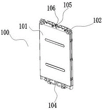
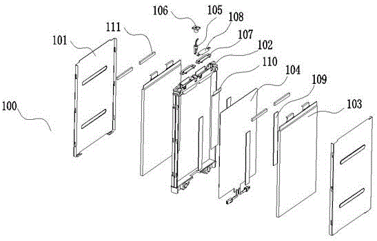
[0065] Depend on figure 1 , figure 2 As shown, the battery module includes:

[0066] The aluminum shell splint 101 is first assembled with the cell support 102 on one side;

[0067] The square polymer lithium-ion battery cell is the designated side of the battery cell 103, which is pasted with green special cotton 109 and the ear of the battery cell 103 is pasted with a silicone sheet 111;

[0068] Select two (or three or more) battery cells 103 pasted with green special cotton 109 and silica gel sheet 111, and then paste a heat-conducting graphite sheet 110 in one of the battery cells 103 (the same side as the green special cotton 109) , and then, the heating sheet 104 is placed between the two electric cores 103 (adhere to the surface of the pasted green special cotton 109), and is wound and fixed with a high-temperature adhesive tape;

[0069] Then place the fixed cell 103 in the inner cavity of the cell bracket 102 where the aluminum shell splint 101 has been combined,...

Embodiment 2

[0094] refer to Figure 5 with 7 , the second cold water plate 315 is the second implementation method, which is to process the curved path of the shape and size of the cooling copper pipe 315a from the aluminum alloy sheet; The two ends of the cooling copper pipe 315a are welded with internal threaded joints, and are threadedly connected with the L-shaped joint 315b; the L-shaped joint 315b is an external threaded joint at one end, and a ferrule-type water pipe joint at one end, and the two ends are connected at a right angle of 90 degrees; The countersunk head screw 313 fixes the second cold water plate 315 to the cavity at the bottom of the battery box lower case 307, and then connects one end of the connecting pipeline 308 to the L-shaped joint 315b of the second cold water plate 315, and the adapter 309 is connected to the vehicle. The connection of the cooling water circuit can form a complete water circuit cooling cycle device, which can realize the external liquid coo...

Embodiment 3

[0096] More than two battery cells 103 are placed in the battery cell holder 102. When the battery cells 103 adopt two or more multi-winding cores to continuously wind the battery cores 411, the two or more continuous winding battery cores 411 are bundled together to form a parallel The battery core electrode group is continuously wound, and the installation structure of the tabs is riveted.

[0097] Two or more multi-roll core continuous winding battery cores 411 are bundled together to form a parallel battery core. The outer layer is covered with an insulating bag 409 (PE insulating bag). The insulating bag 409 is installed in the battery support 102 or fixed In the cell casing 416, the cell casing 416 is installed in the cell support 102. The connection between the cell casing 416 and the casing cover 403 is provided with an insulating bracket 413 (PE insulating bracket), and the cell casing 416 and the casing cover The plate 403 is sealed by laser welding; each multi-roll ...


PUM


Abstract

The invention discloses a new energy power battery. The new energy power battery comprises a battery box upper cover, a power battery module and a battery box lower casing, wherein the power battery module comprises an electric core bracket, more than two electric cores and an aluminum casing clamp plate; the electric cores are arranged in the electric core bracket, and the two outermost sides of each electric core are tightly attached to the aluminum casing clamp plate. The new energy power battery is characterized in that Lvte cotton is adhered to one surface of each electric core, and a silica gel sheet is adhered onto an electrode lug of each electric core; after the two electric cores are adhered with the Lvte cottons and the silicon rubber sheets, a heat conduction graphite sheet is adhered onto the surface, adhering with the Lvte cotton, of one electric core, a heating plate is arranged between the two electric cores, and the two side surfaces of the heating plate are respectively adhered with the Lvte cotton surfaces; a temperature sensor is connected with the heat conduction graphite sheet; a water cooling system is arranged at the exterior of the battery box lower casing, and a connecting structure of positive and negative electrode lugs of each electric core adopts laser welding or riveting type. The new energy power battery has the advantage that the water cooling heat radiating and heating functions are simultaneously realized.

Description

technical field [0001] The invention relates to the field of new energy power batteries, and more specifically, the invention relates to a new energy power battery. Background technique [0002] New energy vehicles refer to vehicles with advanced technical principles, new technologies and new structures that use unconventional vehicle fuels as power sources. [0003] As a new type of clean energy, lithium-ion power batteries have been widely used in energy storage systems in new energy vehicles due to their advantages such as high energy density, good safety, light weight, and long cycle life. Especially in the field of electric vehicle energy storage, lithium-ion power batteries have become the preferred battery type. [0004] When the lithium-ion power battery is charged and discharged at a high temperature above 65°C, the battery will swell, causing the battery to fail or cause safety problems. However, the power battery has a large operating current and produces a large...

Claims


Application Information

Patent Timeline
IPC IPC(8): H01M10/613H01M10/615H01M10/617H01M10/625H01M10/647H01M10/6555H01M10/6567H01M10/657H01M10/0587H01M2/20H01M2/26H01M2/02
CPCH01M10/0587H01M10/613H01M10/615H01M10/617H01M10/625H01M10/647H01M10/6555H01M10/6567H01M10/657H01M2220/20H01M50/10H01M50/50H01M50/531Y02E60/10Y02P70/50
Inventor 章波叶建良
Owner JIANGXI DIBIKE
Why Eureka
Try Eureka