Magnetic coupling commutation type transfer circuit and use method thereof

A transfer circuit, magnetic coupling technology, applied in the direction of DC network circuit devices, circuit devices, electrical components, etc., can solve the problems of low current capacity, large loss, unclear influencing factors, etc., to reduce the voltage level and volume, Withstand voltage requirements and low cost, the effect of bidirectional current transfer

Active Publication Date: 2017-01-25
XI AN JIAOTONG UNIV
View PDF2 Cites 8 Cited by
  • Summary
  • Abstract
  • Description
  • Claims
  • Application Information

AI Technical Summary

Problems solved by technology

However, the current limiting mechanism of liquid metal magnetic shrinkage and its influencing factors are still unclear, and there is a lack of a complete mathematical model of magnetic fluid during the shrinkage process.
[0005] In addition, a current limiting scheme based on high-power power electronic devices has been proposed internationally, but due to the high cost of electronic and electronic devices, low current capacity, and large loss, it is still in the research and exploration stage.

Method used


Image

  • Magnetic coupling commutation type transfer circuit and use method thereof
  • Magnetic coupling commutation type transfer circuit and use method thereof
  • Magnetic coupling commutation type transfer circuit and use method thereof

Examples


Embodiment Construction

[0026] The following detailed description is merely exemplary in nature and not intended to limit application and uses. Furthermore, there is no intention to be bound by any expressed or implied theory presented in the preceding technical field, background, brief summary or the following detailed description. Unless expressly stated to the contrary, the word "comprise" and its various variations should be understood as implying the inclusion of stated elements but not excluding any other elements.

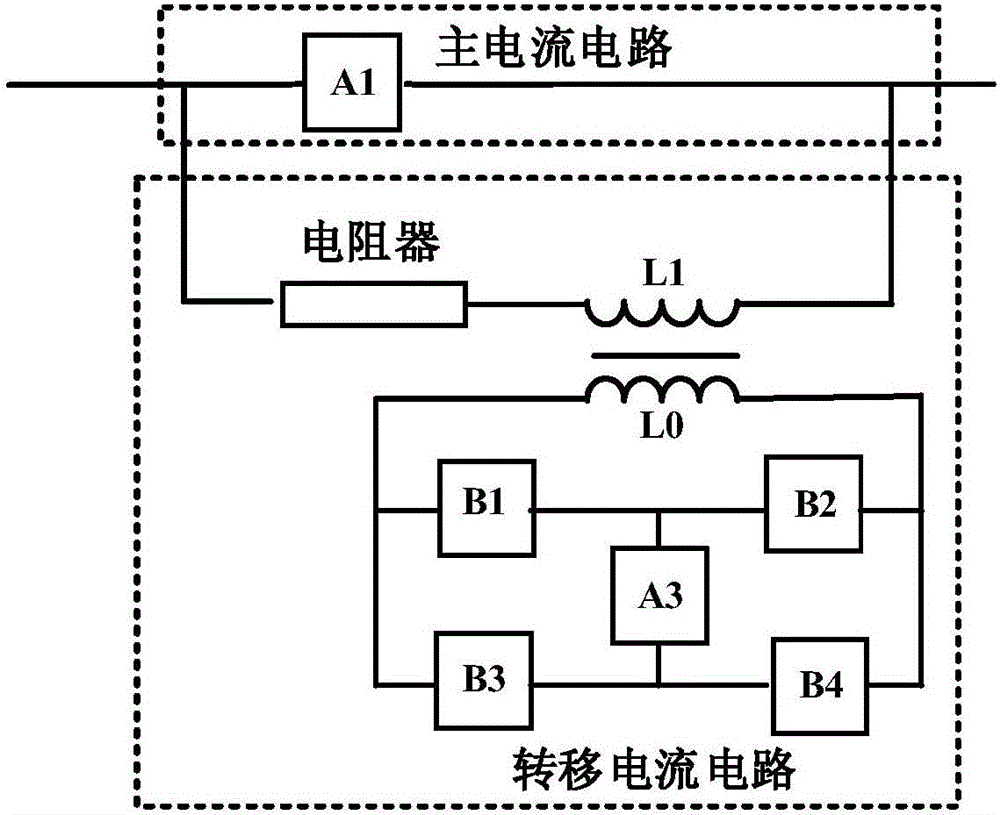
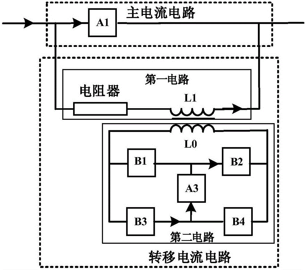
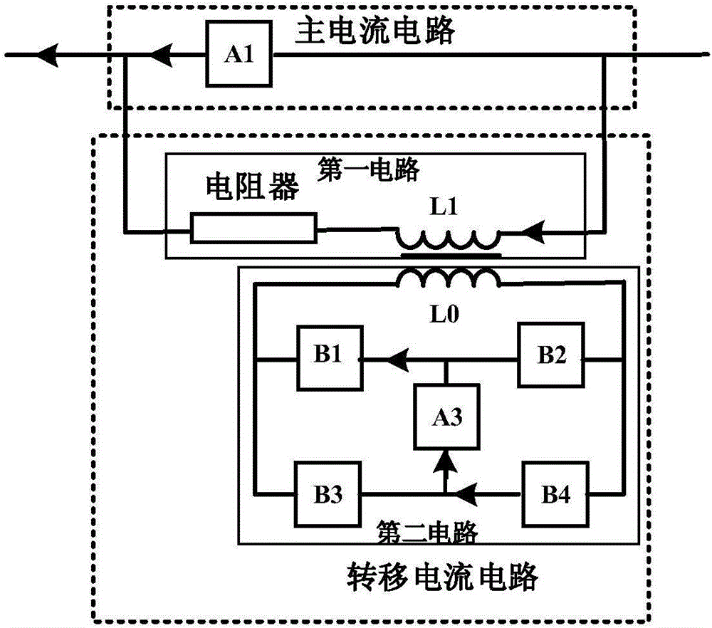
[0027] In one embodiment, a magnetic coupling commutation transfer circuit is disclosed, the circuit includes a main current circuit, a transfer current circuit and an access port;

[0028] The main current circuit is used to continuously carry current or conduct current temporarily;

[0029] The transfer current circuit is used to bear the current transferred from the main current circuit;

[0030] The access port is used for connecting with external systems.

[0031] The trans...


PUM


Abstract

The invention discloses a magnetic coupling commutation type transfer circuit and a use method thereof. The magnetic coupling commutation type transfer circuit comprises a main current circuit and a transfer current circuit, wherein the main current circuit is formed by connecting a mechanical switch, a power electronic device, a current limiter, a resistor and one or more of conducting wires in series or parallel; the transfer current circuit comprises a first circuit and a second circuit; the first circuit is formed by connecting an inductor L1 at a secondary side and a resistor in series; the second circuit is formed by connecting a third circuit A3, power semiconductor devices or triggering gaps B1-B4, and an inductor L0 at a primary side in series, and the third circuit consists of a precharging capacitor or a superconduction inductor. The magnetic coupling commutation type transfer circuit has the advantages that the voltage produced by a voltage transformer is used for directly transferring current to the resistor, the process of transferring the current into the capacitor or the power electronic device is not needed, and compared with the prior art, the current limiting speed and reliability are higher; a capacitor charging unit can be isolated from a direct current system, the voltage class and size of the charging unit are obviously reduced, and the action reliability is improved.

Description

technical field [0001] The disclosure belongs to the field of electronic circuits, in particular to a magnetic coupling commutation transfer circuit and a method for using the same. Background technique [0002] Due to the high rate of rise of the short-circuit current of the DC distribution network, a large short-circuit current will bring many threats to the safe and stable operation of the DC power system. By limiting the short-circuit current, the impact of the short-circuit current on the system and equipment can be significantly reduced, the safety and reliability of the medium-voltage DC power grid can be improved, and the breaking pressure of the DC circuit breaker can be reduced. In order to limit the short-circuit fault current in the medium-voltage DC power distribution system, domestic and foreign research institutions have carried out a lot of research work, which can be roughly divided into superconducting current limiting, liquid metal current limiting and hyb...

Claims


Application Information

Patent Timeline
Patent Type & Authority Applications(China)
IPC IPC(8): H02J1/00
CPCH02J1/00
Inventor 吴益飞杨飞荣命哲纽春萍吴翊胡杨
Owner XI AN JIAOTONG UNIV
Why Eureka
Try Eureka