
Camera protection system

A technology for protecting systems and cameras, applied to components of TV systems, image communications, TVs, etc., can solve problems such as reduced production efficiency, camera system damage, and tool bolt breakage, so as to increase work reliability and environmental adaptability , the effect of prolonging the service life

Inactive Publication Date: 2017-01-25
郑州市物联网产业技术创新研究院有限公司
View PDF8 Cites 10 Cited by
  • Summary
  • Abstract
  • Description
  • Claims
  • Application Information

AI Technical Summary

Problems solved by technology

For example, in the earth pressure balance shield machine, the earth pressure sealed cabin is a visual blind area, the flow state of the muck in the earth pressure sealed cabin, the particle size of the rock after being squeezed and crushed by the cutterhead cutter, and whether there are cutter bolts Abnormal situations such as breakage or the entire tool falling off, the operator cannot directly perceive it through vision, and can only judge by experience. It is also difficult to know abnormal situations such as bolt breakage, which will not only cause production accidents, but also reduce production efficiency
[0004] The application of the traditional shield cutter head monitoring system in actual projects has disadvantages such as high safety risks, high economic costs, and long construction periods.
At present, the working status of the cutter head of the shield machine and the mud condition of the soil bin are generally observed through the camera, but because the working environment of the camera is relatively harsh, its working temperature cannot be guaranteed, which will have a great impact on the service life of the camera
[0005] In addition, when it is applied to shield machine monitoring, especially the earth pressure balance shield machine, its working environment is poor. When the warehouse is full, the camera system works under the friction of the soil, and sometimes there will be broken steel bars , foreign matter with hard texture, etc. There are many sundries, which may cause damage to the camera system, and even directly damage the camera if it is serious, and the observation window is often covered by mud, making the camera unable to observe

Method used


Image

  • Camera protection system
  • Camera protection system
  • Camera protection system

Examples


Embodiment Construction

[0034] In order to facilitate the understanding of the present invention, the present invention will be described in more detail below with reference to the drawings and specific embodiments. The drawings show preferred embodiments of the present invention. However, the present invention can be implemented in many different forms and is not limited to the embodiments described in this specification. On the contrary, the purpose of providing these embodiments is to make the understanding of the disclosure of the present invention more thorough and comprehensive.

[0035] It should be noted that, unless otherwise defined, all technical and scientific terms used in this specification have the same meaning as commonly understood by those skilled in the technical field of the present invention. The terms used in the description of the present invention are only for the purpose of describing specific embodiments, and are not used to limit the present invention. The term "and / or" as u...


PUM


Abstract

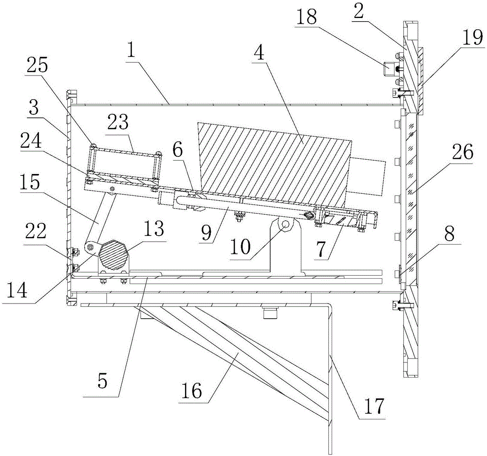
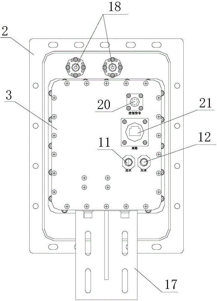
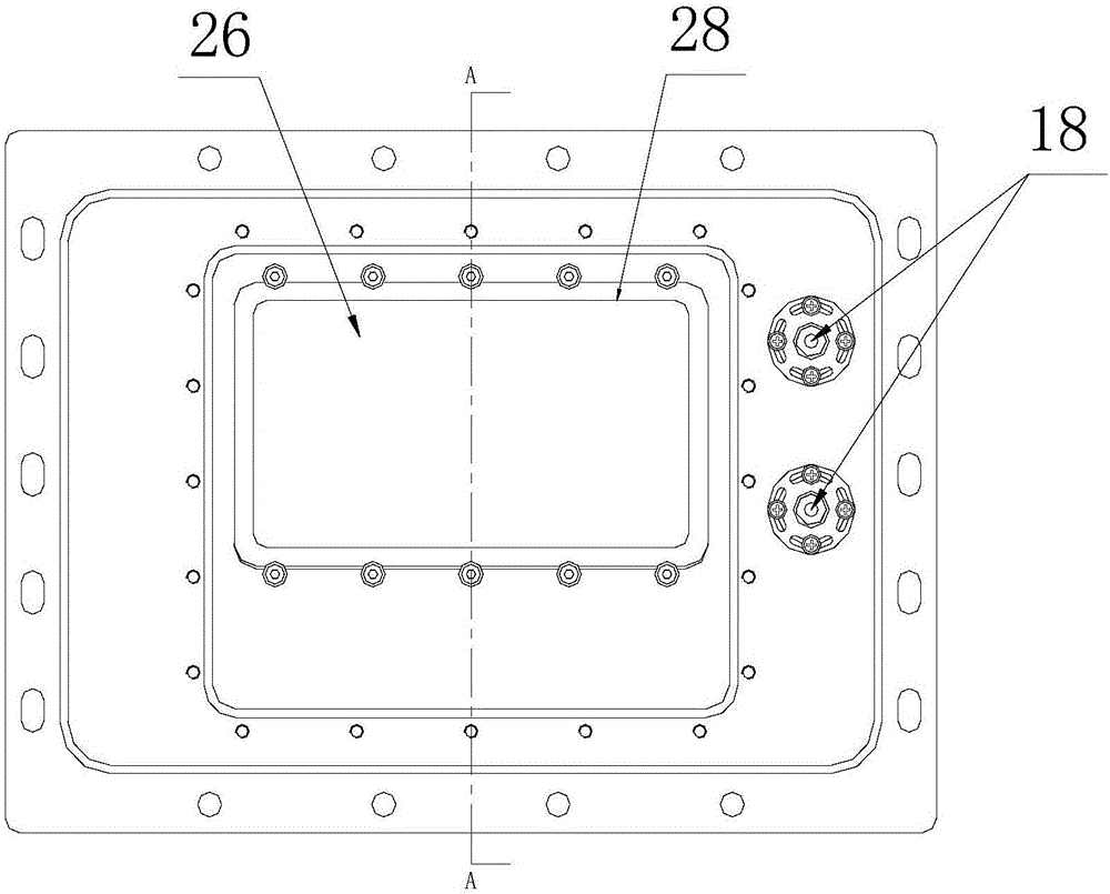
The invention discloses a camera protection system comprising a closed casing for closed installation of a camera, a temperature control device for adjusting the temperature inside the closed casing, a fixing device for fixing the camera, a control circuit, and a window cleaning device, the closed casing comprises a front panel, a casing and a rear panel which are enclosed in one, the front panel is provided with a transparent observation window which is arranged opposite to the lens of the camera for external observation, the fixing device for fixing the camera is arranged in the casing, a window cleaning device is arranged on the outer side of the observation window, the rear panel is provided with a communication interface for communicating with the camera, a power supply and a communication socket electrically connected with the control circuit. The camera protection system can effectively improve the environmental adaptability of the camera work, prolong the service life of the camera and the supporting electronic device, and enhance the working reliability of the camera.

Description

Technical field [0001] The invention relates to a camera protection system, in particular to a camera protection system suitable for a special working environment. Background technique [0002] In today's natural environment, there are many occasions where video monitoring is required but cannot allow operators to enter, such as deep sea, fire field, outer space, etc. In such occasions, robots or manipulators are generally used to carry the camera in-depth observation point for monitoring, but such occasions often have special working environments such as high pressure, high temperature, high cold, and high humidity, which seriously affects the service life of the camera and supporting electronic devices Therefore, it is necessary to provide a system to protect the camera, so as to ensure the service life and working reliability of the camera. [0003] As a special working environment, in the process of tunnel excavation, real-time monitoring of the working status of the tunneling...

Claims


Application Information

Patent Timeline
IPC IPC(8): H04N5/225H05K7/20
CPCH05K7/20209H05K7/20281H04N23/51H04N23/50
Inventor 张涛林昕闫重强谷开放雷莹莹楚燕
Owner 郑州市物联网产业技术创新研究院有限公司
Learn More