Three-dimensional printing device with injector head capable of being vibrated

A printing device and spray head technology, which is applied in coating devices, manufacturing auxiliary devices, processing and manufacturing, etc., can solve the problems of loose structure of 3D printed parts, weak product compactness, poor mechanical properties, etc., and achieve quality and Improvement of appearance quality, improvement of quality and appearance quality, and high mechanical strength

Active Publication Date: 2017-02-01
SHUNDE POLYTECHNIC
View PDF5 Cites 29 Cited by
  • Summary
  • Abstract
  • Description
  • Claims
  • Application Information

AI Technical Summary

Problems solved by technology

[0003] Material extrusion 3D printing device and pneumatic powder flow 3D printing device are two common 3D molding equipment; among them, the material extrusion type belongs to the fusion deposition forming method, and the pneumatic powder flow type belongs to the directed energy deposition type additive However, whether it is fused deposition or directed energy deposition, there are disadvantages, that is, the structure of 3D printed parts is loose, the product is not compact, and the mechanical properties are p

Method used


Image

  • Three-dimensional printing device with injector head capable of being vibrated
  • Three-dimensional printing device with injector head capable of being vibrated
  • Three-dimensional printing device with injector head capable of being vibrated

Examples


Embodiment 1

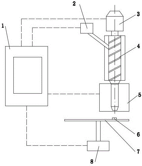
[0038] like figure 1 As shown, it is a 3D printing device with a vibrating ejector head, including a control system 1, a powder supply system 2, a motor drive system 3, a screw extrusion system 4, a first ejector head 5, a workbench 7 and a working table. Table moving system 8; wherein the first injection head 5 is connected to the lower end of the screw extrusion system 4 and communicated with its discharge port, and the motor drive system 3 drives the screw to rotate to complete the screw, extrusion and melting of the material And transport materials to the first injection head 5, the motor drive system 3, the screw extrusion system 4 and the first injection head 5 are integrated and can move horizontally in the X-axis and Y-axis directions above the workbench 7 , the workbench moving system 8 drives the workbench 7 to move vertically up and down, and the control system 1 controls the powder supply system 2, the motor drive system 3, the screw extruding system 4, the first s...

Embodiment 2

[0045] like Figure 9 As shown, it is a 3D printing device in which the ejection head can vibrate, including a control system 1, a worktable 7, a worktable moving system 8, a second ejection head 9, a wire feeding mechanism 10, a guide sleeve 12 and a wire winding material The wire feeding reel 13; wherein the wire material 11 on the wire feeding reel 13 passes through the guide sleeve 12, and the wire feeding motor on the wire feeding reel 13 drives the wire material 11 passing through the guide sleeve 12 to enter the wire feeding mechanism 10 , the second injection head 9 is connected to the lower end of the wire feeding mechanism 10 and communicates with its discharge port. Horizontal movement in the axial direction, the workbench moving system 8 drives the workbench 7 to move vertically up and down, and the control system 1 controls the workbench moving system 8, the second spray head 9, the wire feeding mechanism 10 and the wire feeding plate 13 respectively The work of ...


PUM


Abstract

The invention relates to a three-dimensional printing device with an injector head capable of being vibrated. The device comprises a control system, a screw type extrusion system (or wire feeder), the injector head, a workbench and a workbench moving system. The injector head is connected to the lower end of the screw type extrusion system (or wire feeder) and made communicated with a discharge outlet of the screw type extrusion system (or wire feeder). The screw type extrusion system (or wire feeder) conveys materials to the injector head. The screw type extrusion system (or wire feeder) and the injector head are connected into a whole and can do X-axis and Y-axis direction horizontal movement above the workbench. The workbench moving system drives the workbench to do up-down vertical movement. The control system controls movement of the whole system, and therefore three-dimensional printing is completed. The three-dimensional printing device is characterized in that an ultrasonic vibration device is installed in the injector head. The three-dimensional printing device has the advantages that the structure is simple, molded products are large in density, tensile and impact strength is improved, and product quality is good.

Description

technical field [0001] The invention relates to a 3D printing device, in particular to a 3D printing device with a vibrating ejection head. Background technique [0002] The basic principle of 3D printing processing and forming is: first establish a three-dimensional computer model of the part, then slice it layer by layer, obtain the information data of each layer, and perform layer-by-layer superimposed manufacturing on this basis. This manufacturing method has many advantages due to its own It is widely used in various industries due to its advantages. [0003] Material extrusion 3D printing device and pneumatic powder flow 3D printing device are two common 3D molding equipment; among them, the material extrusion type belongs to the fusion deposition forming method, and the pneumatic powder flow type belongs to the directed energy deposition type additive However, whether it is fused deposition or directed energy deposition, there are disadvantages, that is, the structur...

Claims


Application Information

Patent Timeline
IPC IPC(8): B29C64/106B29C64/209B29C64/307B33Y30/00B33Y40/00
CPCB33Y30/00B33Y40/00
Inventor 陈学锋凃明霞徐言生胡建国柯美元曾宪荣
Owner SHUNDE POLYTECHNIC
Why Eureka
Try Eureka