Double-layer gas exhaust pipeline and application thereof

An exhaust pipe, double-layer technology, applied in the direction of pipe heating/cooling, coating, pipes, etc., can solve the problems of high exhaust pipe temperature and affecting the operating environment of the equipment.

Inactive Publication Date: 2017-02-01
SHANGHAI NAT ENG RES CENT FORNANOTECH
View PDF5 Cites 1 Cited by
  • Summary
  • Abstract
  • Description
  • Claims
  • Application Information

AI Technical Summary

Problems solved by technology

During the working process, the reaction chamber generally has a higher temperature (150°C-400°C), so the exhaust pipe connecting the reaction chamber also has a higher temperature, especially the connection between the vacuum chamber and the external exhaust pipe. The high temperature of some parts will greatly affect the operating environment of the equipment

Method used


Image

  • Double-layer gas exhaust pipeline and application thereof
  • Double-layer gas exhaust pipeline and application thereof

Examples


Embodiment Construction

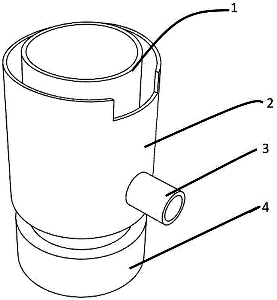
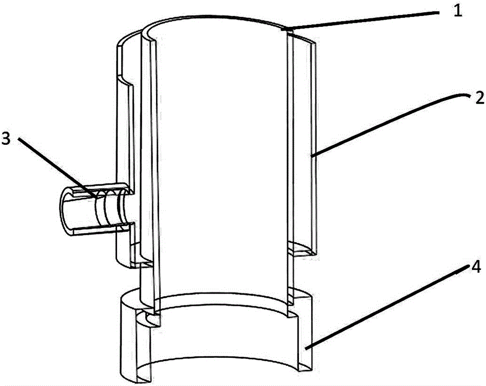
[0016] Such as figure 1 , and shown in 2 are structural schematic diagrams of a preferred embodiment of the present invention. The double-layer exhaust pipe includes an inner pipe 1, an outer pipe 2, and a cooling circulating water joint 3 communicated with the outer pipe , the thick tube 4 connected with the inner tube. Inner tube 1, the upper part is connected to the pipeline in the vacuum reaction chamber; the outer tube 2, the lower part is connected to the inner tube 1, and the upper part is connected to the outer wall of the vacuum chamber of ALD to form a hollow structure; cooling water connector 3, one end is connected to the outer tube The layer tube 2 forms a passage with the hollow structure between the inner and outer tubes, and the other end is used to connect the cooling circulating water; the inner diameter of the thick tube 4 is the same as the outer diameter of the inner tube, and the upper part is connected with the inner tube, and the lower part is used as t...


PUM


Abstract

The invention discloses a double-layer gas exhaust tube. The double-layer gas exhaust tube comprises an inner-layer tube 1, an outer-layer tube 2, a cooling circulating water joint 3 which communicates with the outer-layer tube and a thick tube 4 which is connected with the inner-layer tube, wherein the upper part of the inner-layer tube 1 is connected with a pipeline in a vacuum reaction cavity; the lower part of the outer-layer tube 2 is connected with the inner-layer tube 1, and the upper part of the outer-layer tube 2 is connected with the outer wall of a vacuum cavity of an ALD (atomic layer deposition) to form a hollow structure; one end of the cooling water joint 3 communicates with the outer-layer tube 2 so as to define a channel with a hollow structure between the inner-layer tube 1 and the outer-layer tube 2, and the other end of the cooling water joint 3 is connected with cooling circulating water; and the inner diameter of the thick tube 4 is the same as the outer diameter of the inner-layer tube, the upper part of the thick tube 4 is connected with the inner-layer tube, and the lower part of the thick tube 4 is used as a connector for connecting a rear-end vacuum gas exhaust pipeline. The gas exhaust tube disclosed by the invention ensures obtaining of vacuum by connecting the vacuum reaction cavity to the vacuum gas exhaust pipeline; and meanwhile, the double-layer structure is designed and cooling water is used, so that a proper working environment of equipment is ensured.

Description

[0001] field of invention [0002] The invention relates to an atomic layer deposition (ALD) system, in particular to a double-layer exhaust pipe for connecting a reaction chamber and a vacuum pumping pipeline in the atomic layer deposition (ALD) system. Background technique [0003] According to the reaction principle of ALD, in the prior art, the reaction precursor enters the ALD reaction chamber through the gas pipeline, and at the same time, a real-time continuous vacuum is obtained by connecting a vacuum pump. During the working process, the reaction chamber generally has a higher temperature (150°C-400°C), so the exhaust pipe connecting the reaction chamber also has a higher temperature, especially the connection between the vacuum chamber and the external exhaust pipe. The high temperature of some parts will greatly affect the operating environment of the equipment. Contents of the invention [0004] In order to overcome the deficiencies of the prior art, the present...

Claims


Application Information

Patent Timeline
Patent Type & Authority Applications(China)
IPC IPC(8): F16L53/00F16L9/18C23C16/455
CPCC23C16/4412C23C16/45544F16L9/18F16L53/32
Inventor 何丹农尹桂林卢静金彩虹
Owner SHANGHAI NAT ENG RES CENT FORNANOTECH
Why Eureka
Try Eureka