Mixed light source device and light emitting control method thereof, and projection system

A technology of mixed light source and luminous control, applied in the field of projection, can solve the problem of no infrared image display, etc., and achieve the effect of a wide range of applications

Active Publication Date: 2017-02-01
APPOTRONICS CORP LTD
View PDF12 Cites 8 Cited by
  • Summary
  • Abstract
  • Description
  • Claims
  • Application Information

AI Technical Summary

Problems solved by technology

[0003] For the infrared light region with a wavelength above 780nm invisible to the human eye, it is mainly produced in the night environment. In this environment, there are some requirements for the visibility of infrared light, such as in military operations, but the existing projection system has not yet Technology for displaying infrared images

Method used


Image

  • Mixed light source device and light emitting control method thereof, and projection system
  • Mixed light source device and light emitting control method thereof, and projection system
  • Mixed light source device and light emitting control method thereof, and projection system

Examples


Embodiment 1

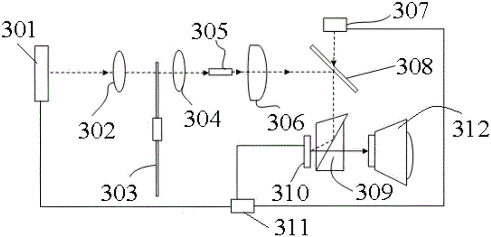
[0029] Such as figure 1 Shown is the projection system of this embodiment, including the system including a main light source 301, a first collection lens 302, a color wheel 303, a second collection lens 304, a square rod 305, a relay system 306, an infrared light source 307, and a dichroic film 308 , a TIR (Total Internal Reflection) prism 309 , a DMD (Digital Mirror Device, Digital Micromirror Device) 310 , a controller 311 and a projection lens 312 .

[0030] The main light source 301, the first collecting lens 302, the color wheel 303, the infrared light source 307, and the controller 311 together constitute the mixed light source device of the system.

[0031]The main light source 301 is a 445nm blue laser for emitting blue laser light as excitation light, and 307 is an 800nm ​​IR (infrared, infrared) laser.

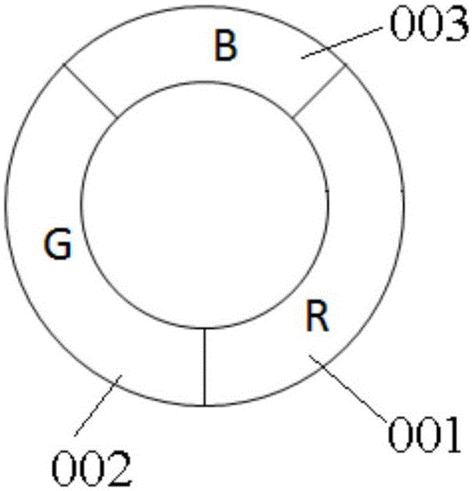
[0032] The color wheel 303 is used as the color light generating device of the mixed light source device, and its structure is as follows: figure 2 As shown, it ...

Embodiment 2

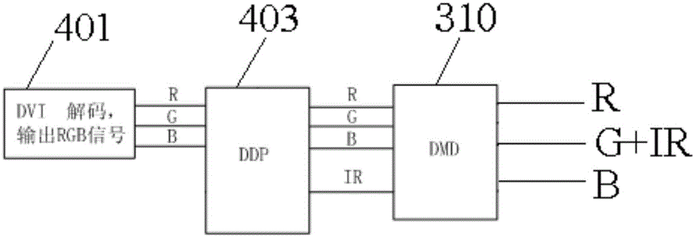
[0048] On the basis of the implementation of Case 1, the IR light is turned on in the three segments of the RGB color wheel, and the DMD outputs the time-series RGB visible light image and the time-series IR light image with RGB signals at the same time. The principle of the control part is as follows Figure 5 As shown, the digital video interface 401 inputs RGB image signals and then transmits them to the DMD 310 through the DDP 403 , and the DDP 403 is connected to the main light source 301 and the infrared light source 307 . While RGB visible light is output, the light emitting device also outputs IR1, IR2, and IR3 infrared lights corresponding to R, G, and B lights.

[0049] That is, the DDP 403 generates an R control signal based on the R image signal, a G control signal based on the G image signal, a B control signal based on the B image signal, a first IR control signal based on the R image signal, and a second IR control signal based on the G image signal. The control...


PUM


Abstract

The invention discloses a mixed light source device and a light emitting control method thereof, and a projection system. The mixed light source device is composed of a main light source emitting exciting light, an infrared light source emitting infrared light, a color wheel, a controller, and an optical modulator. The color wheel generates tri-visible light under irradiation of exciting light. The controller connected with the main light source and the infrared light source is used for outputting a visible light control signal and controlling emission of infrared light based on the visible light control signal by controlling turning-on and turning-off states of the infrared light source. An optical modulator modulates the tri-visible light according to a visible light image signal; and the infrared light is modulated based on the visible light image signal. According to the invention, a visible projection image and an infrared projection image are formed on a same screen by the projection system, so that the display function is extended and thus the product has high competitiveness and a wider application range.

Description

technical field [0001] The invention relates to the field of projection technology, in particular to a mixed light source device, a lighting control method thereof, and a projection system. Background technique [0002] At present, spatial light modulators are widely used in the field of projection display. Spatial light modulators generally include LCD (Liquid Crystal Display, liquid crystal display), LCOS (Liquid Crystal on Silicon, liquid crystal with silicon, also known as liquid crystal on silicon), DMD (Digital Mirror Device, Digital Micromirror Device, digital micromirror device), etc., the single-chip spatial light modulator projection system realizes color projection display based on time-sequentially switched visible light. widely used in the market. In terms of light sources for projection systems, semiconductor lasers excite different fluorescent pink segments on the color wheel to form different visible lights. This method has the advantages of high light effic...

Claims


Application Information

Patent Timeline
IPC IPC(8): G03B21/20
Inventor 郭祖强胡飞侯海雄李屹
Owner APPOTRONICS CORP LTD
Why Eureka
Try Eureka