Permanent magnetic brushless direct current motor low torque ripple Hall fault tolerance control method

A permanent magnet brushless DC, brushed DC motor technology, applied in torque ripple control, motor generator control, electronic commutation motor control and other directions, can solve problems such as life and property threats, Hall position sensor failure, sudden stagnation, etc. , to achieve the effect of low cost, reducing electromagnetic torque ripple and increasing stability

Active Publication Date: 2017-02-01
HARBIN UNIV OF SCI & TECH
View PDF3 Cites 15 Cited by
  • Summary
  • Abstract
  • Description
  • Claims
  • Application Information

AI Technical Summary

Problems solved by technology

[0004] At present, vector control technology is more and more widely used in the control of permanent magnet brushless DC motors. The high-performance vector control technology greatly reduces the torque ripple of the motor. Since vector control requires continuous rotor position information, the rotor position used Sensors (such as: photoelectric encoders, resolvers, etc.) are expensive, their stability is easily affected by the environment, and the cost of the control system is greatly increased in the low-cost field. Therefore, the low-cost vector control method based on the Hall position senso

Method used


Image

  • Permanent magnetic brushless direct current motor low torque ripple Hall fault tolerance control method
  • Permanent magnetic brushless direct current motor low torque ripple Hall fault tolerance control method
  • Permanent magnetic brushless direct current motor low torque ripple Hall fault tolerance control method

Examples


Embodiment Construction

[0020] Exemplary embodiments of the present invention will be described below with reference to the accompanying drawings. In the interest of clarity and conciseness, not all features of an actual implementation are described in this specification. It should be understood, however, that in developing any such practical embodiment, many implementation-specific decisions must be made in order to achieve the developer's specific goals, such as meeting those constraints related to the system and business, and those Restrictions may vary from implementation to implementation. Moreover, it should also be understood that development work, while potentially complex and time-consuming, would at least be a routine undertaking for those skilled in the art having the benefit of this disclosure.

[0021] Here, it should also be noted that, in order to avoid obscuring the present invention due to unnecessary details, only the device structure and / or processing steps closely related to the ...


PUM


Abstract

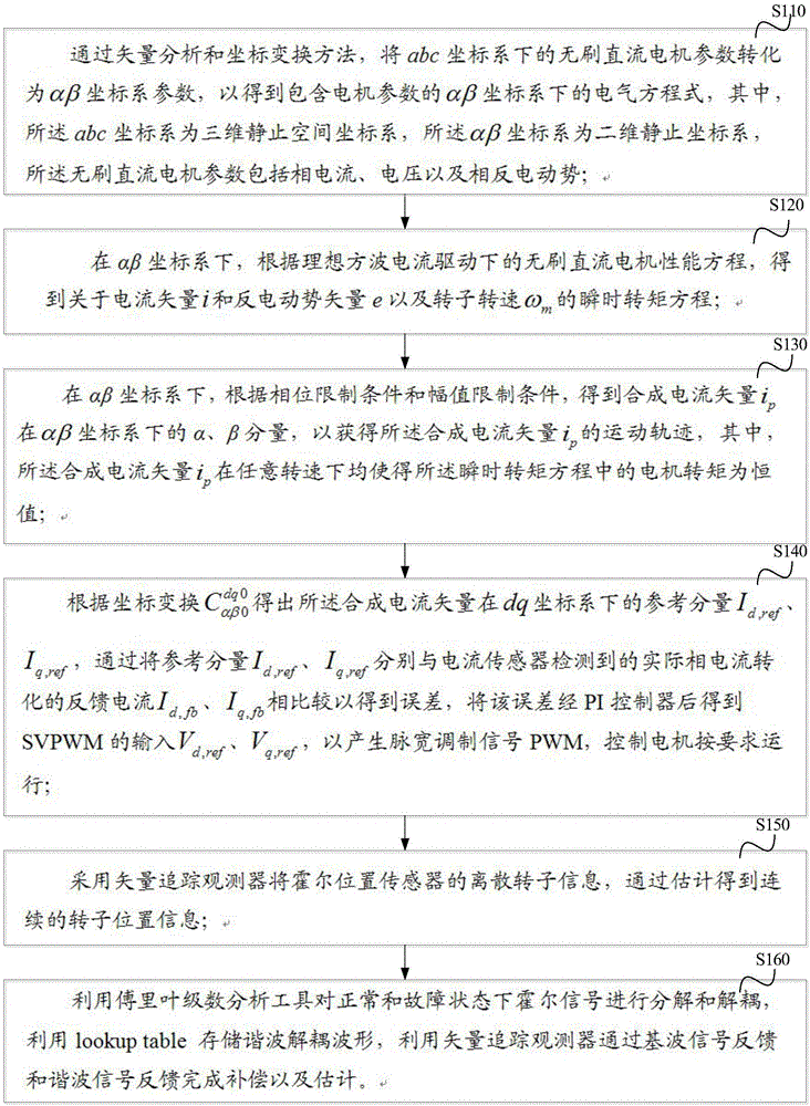
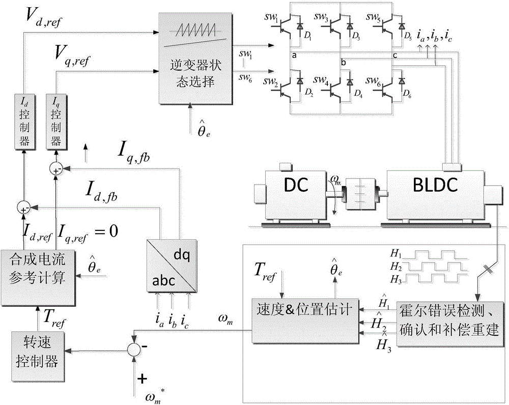
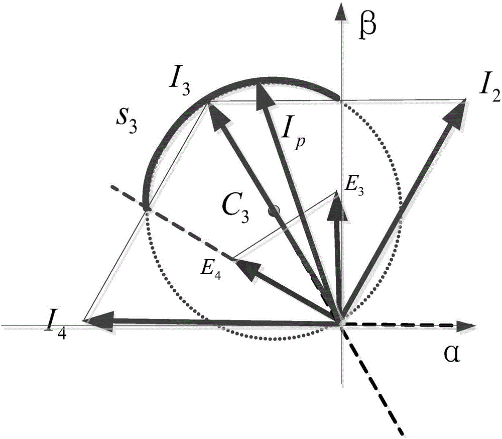
The invention discloses a permanent magnetic brushless direct current motor low torque ripple Hall fault tolerance control method which comprises the following steps: via a vector analysis and coordinate transformation method, brushless direct current motor parameters under an abc coordinate system are converted into alpha and beta coordinate system parameters, an electrical equation comprising electric motor parameters under the alpha and beta coordinate system is obtained; an instantaneous torque equation about a current vector i, a back electromotive force vector e and rotor rotating speed [omega]m is obtained; a movement track of a synthesis current vector ip is obtained; a pulse width modulation PWM is generated, an electric motor is controlled to operate according to requirements, a vector tracking observer is used for subjecting discrete rotor information of a Hall position sensor to estimating operation and then continuous position information can be obtained; a Fourier expansion series analysis tool is used for decomposing and decoupling Hall signals in a normal state and a fault state, a lookup table is used for storing decoupled waveforms of harmonic waves, and the vector tracking observer is used for completing estimating and compensating operation via fundamental wave signal feedback and harmonic wave signal feedback.

Description

technical field [0001] The invention relates to the field of permanent magnet motor control for electric vehicles, in particular to a low-torque ripple Hall fault-tolerant control method for a permanent magnet brushless DC motor. Background technique [0002] Permanent magnet brushless DC motors have higher efficiency and power density than DC motors and induction motors of the same size, so they are widely used in the servo field, as well as electric vehicles, household appliances and other fields. The traditional permanent magnet brushless DC motor is driven by a square wave current with an electrical angle of 120°. Due to the limitation of the inductance of the motor phase winding and the power of the DC power supply, the phase current will not change transiently during commutation, forming a non-ideal square wave current. This in turn leads to commutation torque pulsation. In addition, due to the motor manufacturing process, the counter electromotive force is not ideal, ...

Claims


Application Information

Patent Timeline
IPC IPC(8): H02P6/10H02P21/05
CPCH02P6/10H02P21/05
Inventor 吕德刚都泽源姜彪
Owner HARBIN UNIV OF SCI & TECH
Why Eureka
Try Eureka