A pressure screen rotor rotor

A pressure screen and rotor technology, which is applied in textiles, papermaking, and fiber raw material processing, can solve the problems of increasing rotor rotor resistance, increasing reactive power, and reducing screening efficiency, achieving the effects of reducing resistance, reducing quality, and improving screening efficiency.

Active Publication Date: 2019-05-31
GUANGXI UNIV
View PDF6 Cites 0 Cited by
  • Summary
  • Abstract
  • Description
  • Claims
  • Application Information

AI Technical Summary

Problems solved by technology

In this process, the injection of vortex will increase the resistance of the rotor blade, and the increase of vortex flow will increase the reactive power in the screening process, thus reducing the screening efficiency

Method used


Image

  • A pressure screen rotor rotor
  • A pressure screen rotor rotor
  • A pressure screen rotor rotor

Examples


Embodiment Construction

[0020] The technical solution of the present invention will be further described below in conjunction with the accompanying drawings and embodiments, and the technical solution of the present invention is not limited to the shape described in this example.

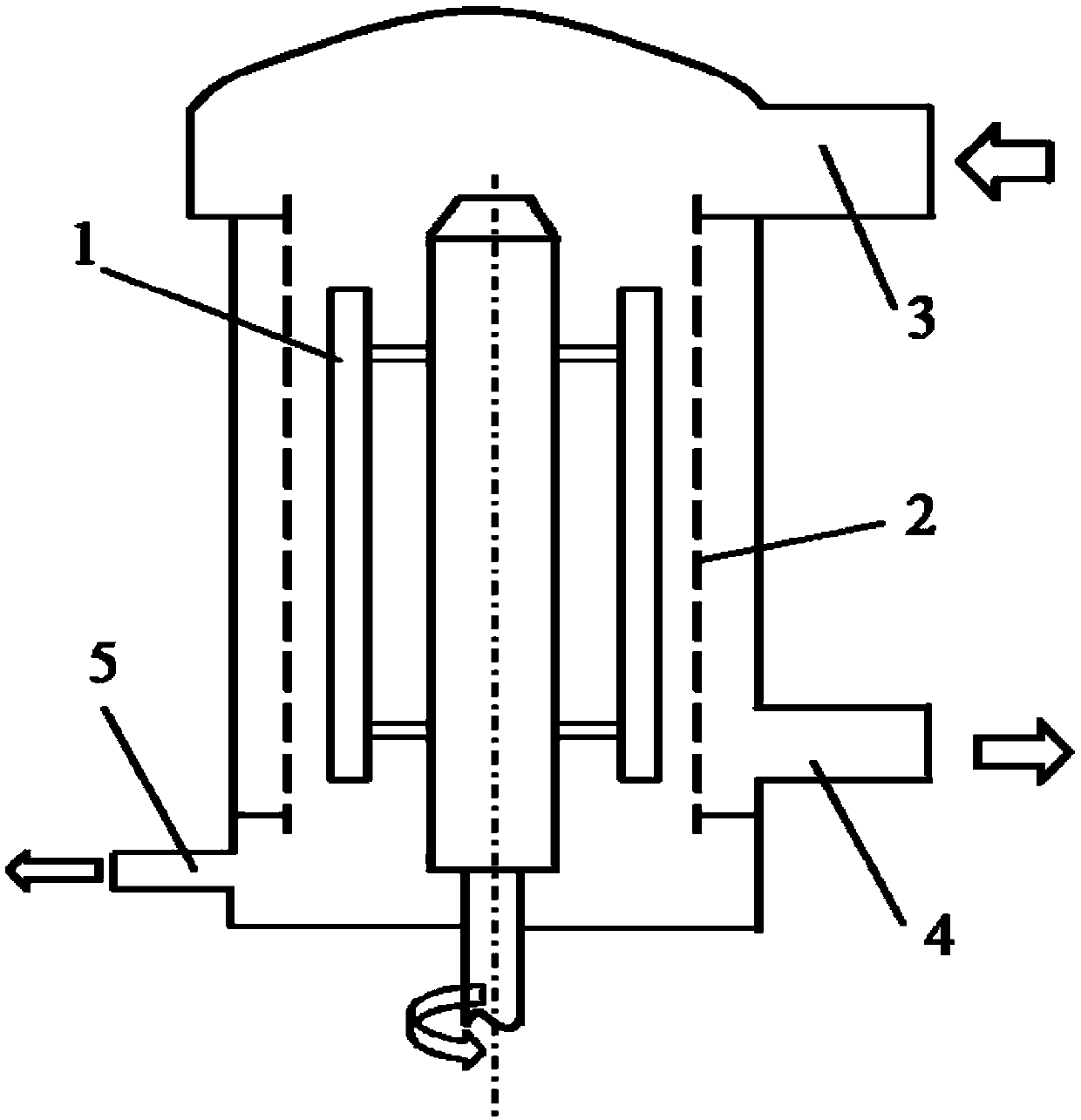
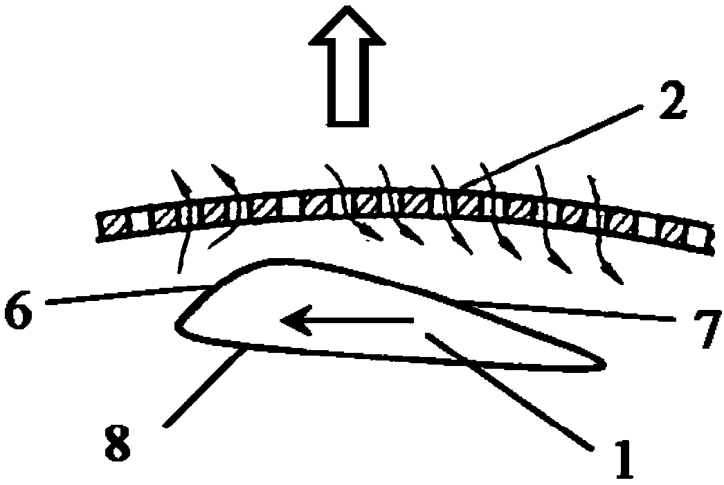
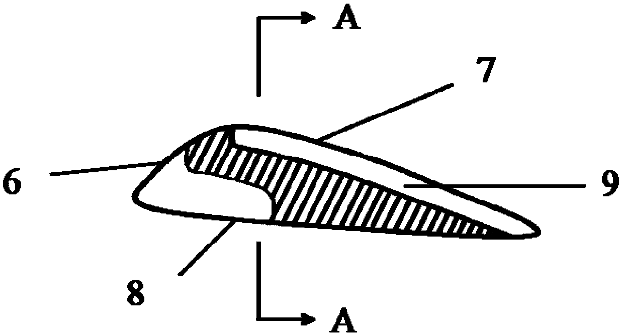
[0021] Traditional rotor pressure screens such as figure 1 and figure 2 As shown, its structure is mainly composed of a rotor rotor 1, a sieve plate 2, a pulp inlet pipe 3, a good pulp pipe 4 and a slag discharge pipe 5, wherein the rotor rotor 1 includes a mounting surface 8, a pulp pushing surface 6 and a pulp suction surface 7, The pushing surface 6 is connected with the slurry suction surface 7 and forms an outwardly convex arc, and the mounting surface 8 is connected with the rotating shaft to make the rotor rotor rotate. The slurry pushing surface 6 is located at the front of the rotor rotor, and the slurry suction surface 7 is located at the tail of the rotor. .

[0022] The pressure screen rotor rotor of this em...


PUM


Abstract

The invention discloses a rotor rotary wing of a pressure screen. The rotor rotary wing comprises a mounting surface, a pulp pushing surface and a pulp suction surface, wherein the pulp pushing surface and the pulp suction surface are connected to form a protruding arc shape; the pulp suction surface is provided with a plurality of rows of grooves which are parallel to one another; and the arrangement direction of the grooves is parallel to a movement direction of the rotary wing. The rotor rotary wing of the pressure screen is mounted on the pressure screen so that operation resistance can be reduced, the screening energy consumption is reduced, a screening process is moderate and the operation is reliable.

Description

technical field [0001] The invention relates to the field of pulping and papermaking machinery, in particular to a pressure screen rotor rotor. Background technique [0002] There are many kinds of impurities in pulp, typically fibrous and non-fibrous impurities such as sediment, metal particles, plastics, rubber, ink, and fiber bundles produced in the pulping process mixed into the pulp from the outside. In order to maintain good, stable and efficient operation of pulp and paper-related operating units, as well as to ensure good quality of semi-finished and finished products, it is necessary to remove various impurities in pulp. [0003] The pressure screen separates impurities based on the different shapes of impurities and good pulp fibers. Typical rotor pressure screens are as follows: figure 1 As shown, its structure is mainly composed of a rotor rotor 1, a sieve plate 2, a pulp inlet pipe 3, a good pulp pipe 4 and a slag discharge pipe 5, wherein the rotor rotor 1 inc...

Claims


Application Information

Patent Timeline
Patent Type & Authority Patents(China)
IPC IPC(8): D21D5/06
CPCD21D5/06
Inventor 沙九龙李许生覃程荣王双飞
Owner GUANGXI UNIV
Why Eureka
Try Eureka