Explosion-proof fuel oil dehydration and deoxygenation device

An explosion-proof, fuel oil technology, applied in the directions of liquid degassing, separation methods, chemical instruments and methods, etc., can solve the problems of inability to online dehydration and deoxidation, no explosion-proof function, small fuel flow rate, etc. Good economic benefits and the effect of increasing the contact area

Active Publication Date: 2018-11-30
SHENYANG AEROSPACE XINGUANG GRP
View PDF5 Cites 0 Cited by
  • Summary
  • Abstract
  • Description
  • Claims
  • Application Information

AI Technical Summary

Problems solved by technology

[0007] Aiming at the problems existing in the above-mentioned prior art, the present invention provides an explosion-proof fuel oil dehydration and deoxygenation device, which solves the problems in the prior art that the flow rate of the fuel oil is too small, the efficiency is low, the online dehydration and deoxygenation cannot be performed, and the explosion-proof function is not available.

Method used


Image

  • Explosion-proof fuel oil dehydration and deoxygenation device
  • Explosion-proof fuel oil dehydration and deoxygenation device
  • Explosion-proof fuel oil dehydration and deoxygenation device

Examples


Embodiment 1

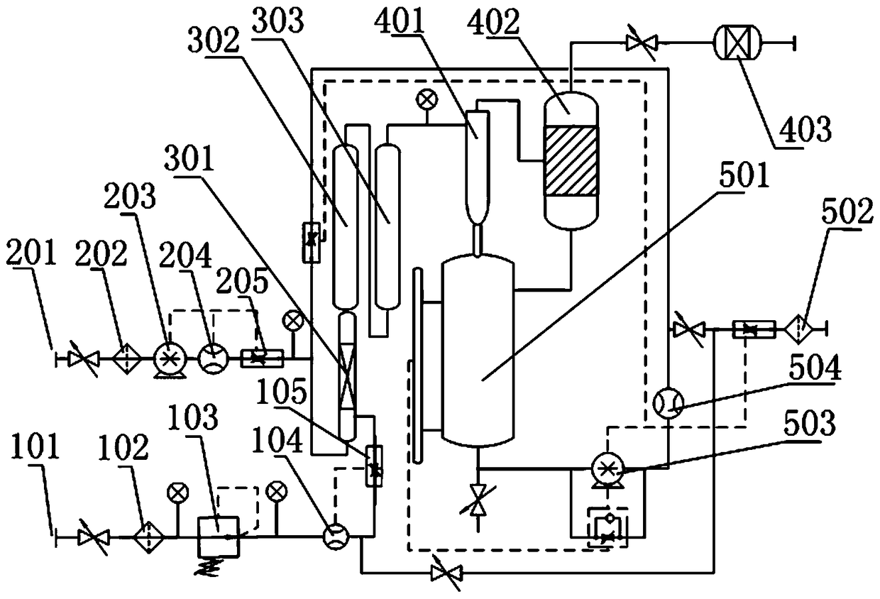
[0021] like figure 1 The explosion-proof fuel oil dehydration and deoxygenation device shown includes an air intake pipeline system, an oil intake pipeline system, an oil-gas mixing system, an oil-gas separation system, a product oil delivery system, and an automatic control system; the oil-gas mixing system includes an oil inlet and an air inlet The Venturi atomizing mixer, gas-liquid static mixer Ⅰ, the gas-liquid outlet of the Venturi atomizing mixer and the gas-liquid inlet of the gas-liquid static mixer Ⅰ are connected by pipelines; the gas-liquid static mixing system is added to the oil-gas mixing system The gas-liquid inlet of the gas-liquid static mixer II is connected to the gas-liquid outlet of the gas-liquid static mixer I through pipelines, and the gas-liquid outlet of the gas-liquid static mixer II is connected to the oil-gas separation system.

[0022] By adding the gas-liquid static mixer II, compared with a single gas-liquid static mixer, the capacity of oil an...

Embodiment 2

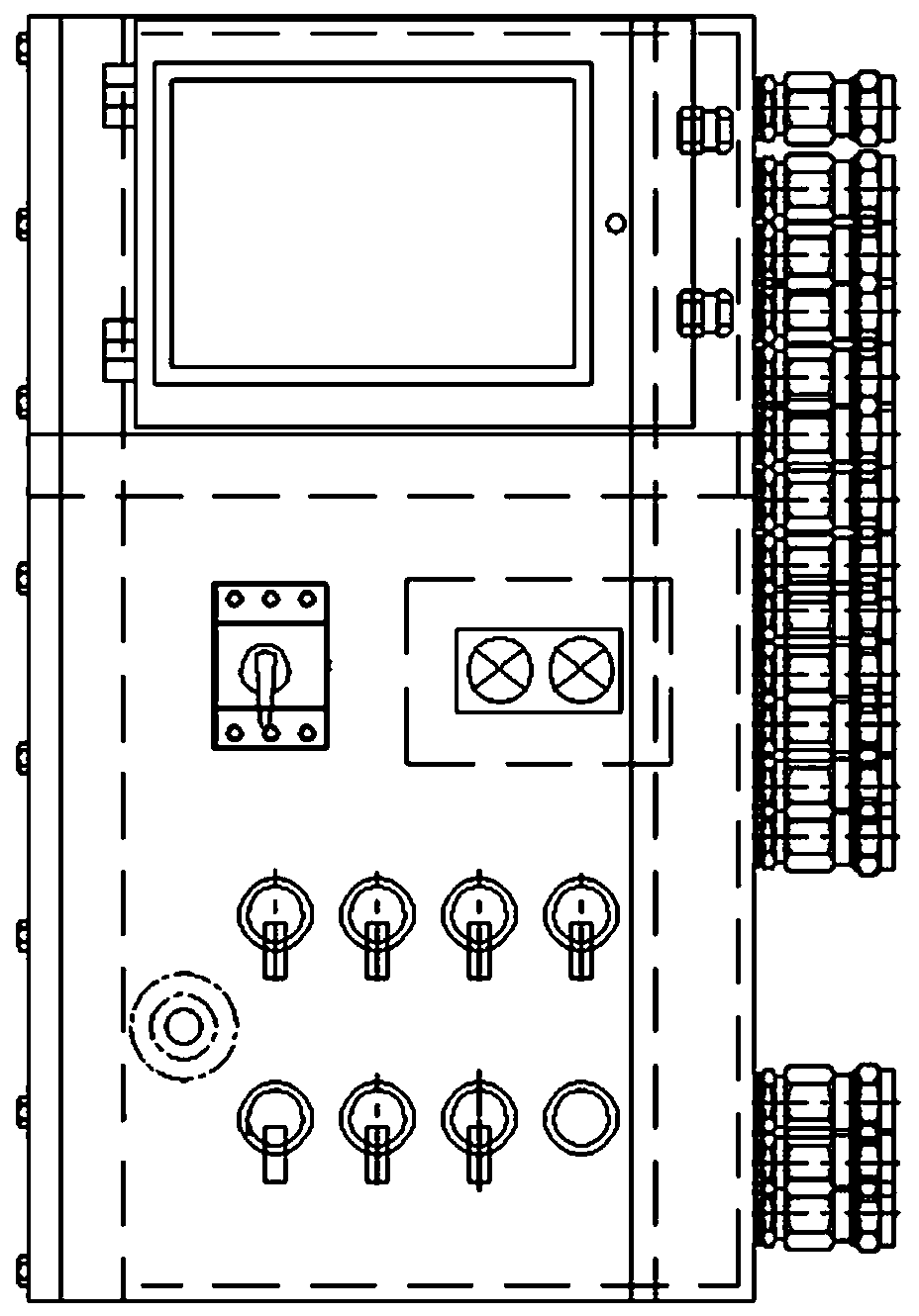
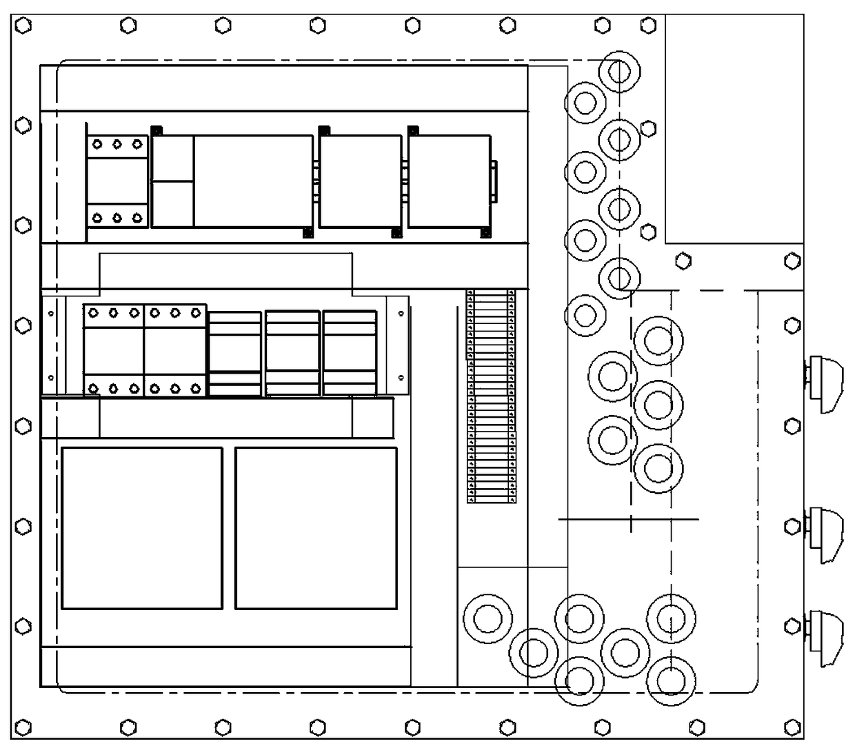
[0040] On the basis of the foregoing embodiment 1, in order to adapt to different working environments and different customer requirements, an explosion-proof device and an explosion-proof design of the entire equipment are added.

[0041] The control box is an explosion-proof control box, and the explosion-proof control box has a shell that can isolate sparks or electric arcs generated by electrical components from the explosive gas in the surrounding environment; it also includes an explosion-proof switch and a cable sealing structure, which are respectively arranged in the explosion-proof control on the casing of the box.

[0042] Among them, the explosion-proof control box is used to accommodate PLC controllers, frequency conversion controllers and other electrical components; the control cable enters the explosion-proof control box through the cable sealing structure, and the cable sealing structure can tightly wrap the cables passing through the house, further strengtheni...


PUM


Abstract

The invention relates to an online fuel oil dehydrating and deoxidizing device, particularly relates to an anti-explosion fuel oil dehydrating and deoxidizing device, and belongs to the technical field of comprehensive guarantee. The device comprises an air inlet pipeline system, an oil inlet pipeline system, an oil-gas mixing system, an oil-gas separating system, a petroleum product conveying system and an automatic control system, wherein a gas-liquid static mixer II is additionally arranged in the oil-gas mixing system. By additionally arranging the gas-liquid static mixer II, the contact area between a fuel and nitrogen is increased, so that the total quantity of fuel oil treated in the periodic time of the replacement reaction is increased, and the separation efficiency of water and the fuel oil and the separation efficiency of oxygen and the fuel oil are improved; by rapidly separating the fuel oil and nitrogen, an online, rapid and high-flow dehydrating and deoxidizing function is realized. By virtue of an anti-explosion design, the reliability and safety of the device are improved, and the demands of different customers are met.

Description

technical field [0001] The invention relates to an online fuel oil dehydration and deoxygenation device, in particular to an explosion-proof fuel oil dehydration and deoxygenation device, which belongs to the technical field of comprehensive guarantee. Background technique [0002] With the development of modern weapon models and the requirements of users for the environment in which products are used, fuel oil needs to be stored for a long time. At present, during the long-term storage of fuel oil, the metal materials of the fuel system components and fuel tanks are in contact with the fuel for a long time, and the water in the fuel will make the metal materials Electrochemical corrosion occurs, and the water in the fuel provides a breeding environment for microorganisms. The growth of microorganisms can accelerate the corrosion of the aluminum alloy of the fuel tank and the oxidation of the fuel. [0003] When the fuel is used at low temperature, the water in the fuel will...

Claims


Application Information

Patent Timeline
Patent Type & Authority Patents(China)
IPC IPC(8): B01D17/035B01D19/00
CPCB01D17/0205B01D19/00
Inventor 祝贺利景月
Owner SHENYANG AEROSPACE XINGUANG GRP
Why Eureka
Try Eureka