Transfer-printing coding method

A pad printing and pad printing machine technology, which is applied in the field of pad printing and coding, can solve the problems of difficult large-volume, continuous pad printing, low pad printing efficiency, and poor clarity, and achieve the effect of improving production efficiency

Active Publication Date: 2017-02-15
CHENGDU OJA AIRCRAFT CABIN EQUIP
View PDF7 Cites 4 Cited by
  • Summary
  • Abstract
  • Description
  • Claims
  • Application Information

AI Technical Summary

Problems solved by technology

[0005] In the pad printing machine and pad printing method disclosed in this patent document, since the surface of the flat plate trans graphic plate is a flat surface, it is relatively easy to grasp the size and position of the graphics formed on it, so the accuracy of pad printing is relatively high, but After the printed object is used for a long time, the ink printed on it is easy to fade and lighten, resulting in poor clarity, and it is difficult to achieve large-scale and continuous pad printing with this pad printing method, and the pad printing efficiency is low

Method used


Image

  • Transfer-printing coding method
  • Transfer-printing coding method
  • Transfer-printing coding method

Examples


Embodiment 1

[0044] A pad printing coding method, comprising the following steps:

[0045] a. Inking step, ink the etched plate 34 through the sealed oil cup 35 of the pad printing coding device to form patterned ink;

[0046] b. Ink dipping step, push the rubber head 32 of the pad printing machine 3 forward to the top of the etching plate 34, then drive the rubber head 32 to descend to contact the etching plate 34, and the rubber head 32 is pressed down to be stained with the ink with the pattern, Then drive the rubber head 32 to rise and return to its original position;

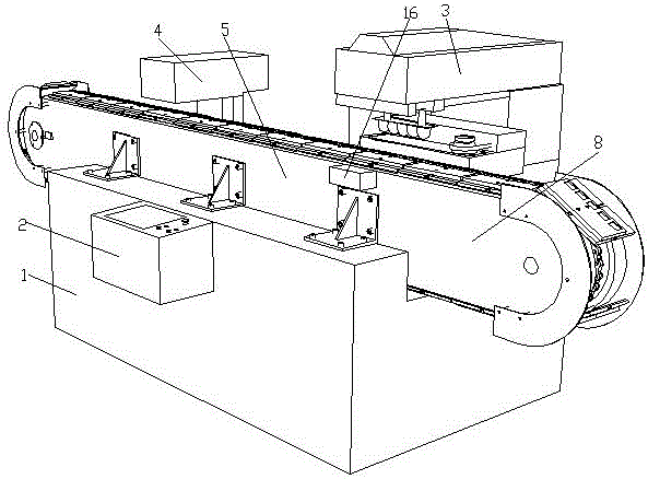
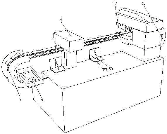
[0047] c. Pad printing step, push the rubber head 32 backward to the top of the supporting plate 52 of the conveying part 5, and then drive the rubber head 32 to press down, and the rubber head 32 will print the ink with the pattern on the mold groove 15. on printed matter;

[0048] d. Coding step, moving the printed item after pad printing to the bottom of the laser coding machine 4 through the conveying part 5, and ...

Embodiment 2

[0051] A pad printing coding method, comprising the following steps:

[0052] a. Inking step, ink the etched plate 34 through the sealed oil cup 35 of the pad printing coding device to form patterned ink;

[0053] b. Ink dipping step, push the rubber head 32 of the pad printing machine 3 forward to the top of the etching plate 34, then drive the rubber head 32 to descend to contact the etching plate 34, and the rubber head 32 is pressed down to be stained with the ink with the pattern, Then drive the rubber head 32 to rise and return to its original position;

[0054] c. Pad printing step, push the rubber head 32 backward to the top of the supporting plate 52 of the conveying part 5, and then drive the rubber head 32 to press down, and the rubber head 32 will print the ink with the pattern on the mold groove 15. on printed matter;

[0055] d. Coding step, moving the printed item after pad printing to the bottom of the laser coding machine 4 through the conveying part 5, and ...

Embodiment 3

[0061] A pad printing coding method, comprising the following steps:

[0062] a. Inking step, ink the etched plate 34 through the sealed oil cup 35 of the pad printing coding device to form patterned ink;

[0063] b. Ink dipping step, push the rubber head 32 of the pad printing machine 3 forward to the top of the etching plate 34, then drive the rubber head 32 to descend to contact the etching plate 34, and the rubber head 32 is pressed down to be stained with the ink with the pattern, Then drive the rubber head 32 to rise and return to its original position;

[0064] c. Pad printing step, push the rubber head 32 backward to the top of the supporting plate 52 of the conveying part 5, and then drive the rubber head 32 to press down, and the rubber head 32 will print the ink with the pattern on the mold groove 15. on printed matter;

[0065] d. Coding step, moving the printed item after pad printing to the bottom of the laser coding machine 4 through the conveying part 5, and ...


PUM


Abstract

The invention discloses a transfer-printing coding method. The transfer-printing coding method comprises the following steps: (a) an ink feeding step, namely feeding ink to an etching plate by using a sealed type oil cup of a transfer-printing coding device; (b) an ink staining step, namely forwards pushing a rubber head of a transfer printer to a position above the etching plate, subsequently driving the rubber head to move down to have contact with the etching plate, and pressing the rubber head downwards to be stained with the ink having patterns; (c) a transfer printing step, namely backwards pushing the rubber head to a position above a supporting plate of a conveying component, and then driving the rubber head to be pressed downwards, wherein the rubber is capable of printing the ink having patterns on a to-be-printed object in a mold groove; (d) a coding step, moving the transfer-printed object to a position below a laser coding machine, and performing laser coding by using the laser coding machine. According to the transfer-printing coding method disclosed by the invention, the laser coding machine is capable of coding the last transfer-printed object during transfer printing of a to-be-printed object of the next period, so continuous operation on large-batch to-be-printed objects can be realized, the production efficiency is greatly improved, and a coded product is high in fineness.

Description

technical field [0001] The invention relates to the technical field of printing technology, in particular to a pad printing coding method. Background technique [0002] Pad printing machine is a kind of printing equipment, which is suitable for printing plastic, toys, glass, metal and ceramics. Pad printing is an indirect intaglio printing technology, which has become a main method for surface printing and decoration of various objects. The whole pad printing process mainly includes several steps of inking, ink scraping, ink dipping and pad printing. First, the ink is sprayed on the etching board, and then the excess ink is scraped off with a retractable scraper; The solvent in the ink in the etching area volatilizes and forms a gel-like surface, and then the glue head descends to the etching plate to absorb ink; the glue head absorbs most of the ink on the etching plate and then rises, at this time, this layer of ink volatilizes again One part, the remaining part of the w...

Claims


Application Information

Patent Timeline
Patent Type & Authority Applications(China)
IPC IPC(8): B41M5/382
CPCB41M5/382
Inventor 项林南
Owner CHENGDU OJA AIRCRAFT CABIN EQUIP
Why Eureka
Try Eureka