Method of welding thermistance chip and down lead

A thermistor and welding method technology, applied in resistors, welding equipment, non-adjustable metal resistors, etc., can solve the problems of voltage resistance drop, short preheating time, large welding temperature difference, etc., and achieve a small reduction in voltage resistance. , the effect of improving lasting reliability and reducing the probability of failure

Inactive Publication Date: 2008-07-30
深圳市伟林高科技股份有限公司
View PDF0 Cites 16 Cited by
  • Summary
  • Abstract
  • Description
  • Claims
  • Application Information

AI Technical Summary

Problems solved by technology

[0009] Using the dip soldering method, because the product is not preheated before soldering or the preheating time is short and insufficient, the product is directly immersed in the solder furnace, the direct soldering temperature is as high as 230±10°C, and the lead-free tin temperature is as high as 270°C, and the product suddenly heats up. , the ceramic body of the chip generates local high temperature. After dipping and soldering, it is directly taken out of the tin furnace, and then it is suddenly cooled, which is easy to damage the internal structure of the chip and cause microcracks inside the product, resulting in the thermistor working in a long-term high-temperature, high-current impact working environment. Under normal circumstances, the cracks continue to expand and cause early failure of the product; and due to the large temperature difference in welding, the process is not easy to control, and there are many human factors; resulting in a significant drop in withstand voltage after welding. After testing, the product withstand voltage drops by 10% to 15%; Box operation, small output
And wave soldering also has defects similar to dip soldering

Method used


Image

  • Method of welding thermistance chip and down lead

Examples


Embodiment Construction

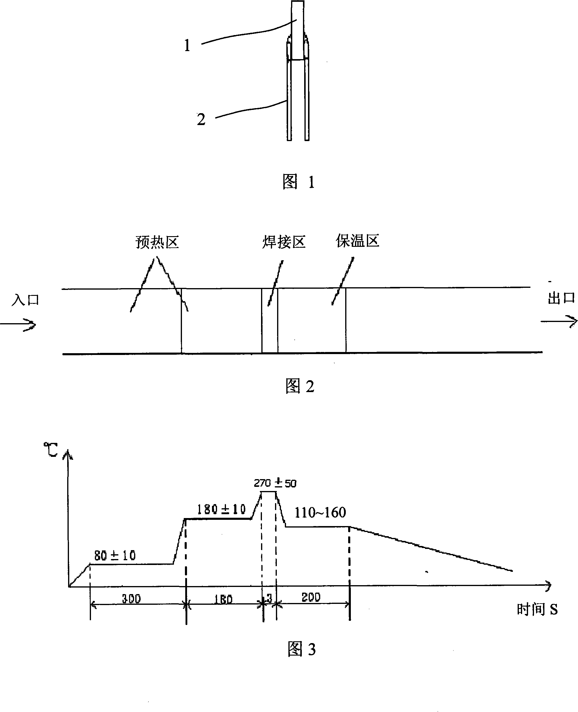
[0022] The invention provides a method for welding a chip and a lead wire of a thermistor, which is used in the thermal resistance manufacturing process to weld the chip and the lead wire manufactured in the previous steps into one, and it includes the following steps:

[0023] In the preparation step, the lead wires are formed on the wire bonding machine according to the required line shape, and then the electrode-plated chips are inserted into the wire row according to the standard to be welded, and the step-type hot air welding machine is started, as shown in Figure 2, the welding machine furnace There are low-temperature preheating zone, high-temperature preheating zone, welding zone and heat preservation zone in sequence from the entrance to the exit. As shown in Figure 3, the temperatures of the low-temperature preheating zone, high-temperature preheating zone and welding zone are respectively set 80±10°C, 180±10°C, 270±50°C, and the temperature of the heat preservation a...


PUM


Abstract

The invention relates to a method for welding a chip and a lead wire of a thermal resistor, comprising the following steps: a lead wire is formed; a chip is inserted with a wire and a staged hot-air welding machine is started heating a low-temperature preheating zone, a high-temperature preheating zone, a welding zone and a heat-keeping zone in a furnace to a preset temperature; the wire rows with a good insertion are sent into the low-temperature preheating zone and the high-temperature preheating zone in sequence for preheating; the preheated chip and the wire row are sent to the welding zone; soldering tin in the lead wire is melted due to the hot air from a hot-air welding gun, which ensures the lead wire and the chip are fixedly welded together; the well welded product is then sent to the heat-keeping zone for carrying out an insulation treatment; after the insulation treatment, the product is moved out from the furnace and is naturally cooled to room temperature. The product is then self-checked, washed and dried in the air for entering the next process. In the invention, welding happens after fully preheating and the welded product is slowly cooled after insulation treatment; therefore, the chip does not experience heat shocks and generates micro-cracks; the product has good durability and liability, and decrease of the withstand voltage of the product is small. The invention has good process controllability and can realize progressive production work, thus having high output.

Description

technical field [0001] The invention relates to a method for manufacturing a thermistor, in particular to a method for welding chips and leads of the thermistor. Background technique [0002] A thermistor is a resistive element whose resistance value changes with temperature. The resistance value increases with temperature, which is called a positive temperature coefficient (PTC) thermistor, and vice versa, it is called a negative temperature coefficient (NTC) thermistor. The thermistor has a wide range of uses according to its special electrical properties. It is mainly divided into: for communication overcurrent protection; for energy-saving lamps and rectifiers for preheating and startup; Compensation, measurement, control; suppression of surge current, etc. [0003] The existing thermistor manufacturing process is as follows: batching ball milling → adhesive preparation → granulation → molding → sintering → electrode → sorting → wire bonding → inserting → welding → enca...

Claims


Application Information

Patent Timeline
Patent Type & Authority Applications(China)
IPC IPC(8): B23K1/012B23K1/20H01C7/00
Inventor 鲍峰石开轩朱同江张金英朱淑宏张刚张永松
Owner 深圳市伟林高科技股份有限公司
Why Eureka
Try Eureka