Eureka AIR delivers breakthrough ideas for toughest innovation challenges, trusted by R&D personnel around the world.

Determination method of producing water for shale gas well, determination method of accumulated liquid and liquid drainage method

A technology for shale gas wells and determination methods, which is applied in the fields of earthwork drilling, wellbore/well components, and special data processing applications, etc. It can solve the problems of large errors, inability to analyze and calculate the height of liquid accumulation, and affect the decision-making of tool running positions, etc. problems, to achieve the effect of reducing bottomhole pressure, avoiding production stoppage and improving drainage efficiency

Active Publication Date: 2017-02-15
CHINA PETROLEUM & CHEM CORP +1
View PDF10 Cites 5 Cited by
  • Summary
  • Abstract
  • Description
  • Claims
  • Application Information

AI Technical Summary

Problems solved by technology

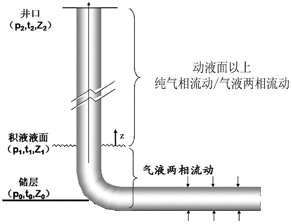
The above methods all judge the bottom of the well by the wellhead conditions, so the error is relatively large. At the same time, the existing methods cannot analyze and calculate the height of the liquid accumulation, which affects the decision-making of the tool running position during the later drainage.

Method used


Image

  • Determination method of producing water for shale gas well, determination method of accumulated liquid and liquid drainage method
  • Determination method of producing water for shale gas well, determination method of accumulated liquid and liquid drainage method
  • Determination method of producing water for shale gas well, determination method of accumulated liquid and liquid drainage method

Examples


Embodiment 1

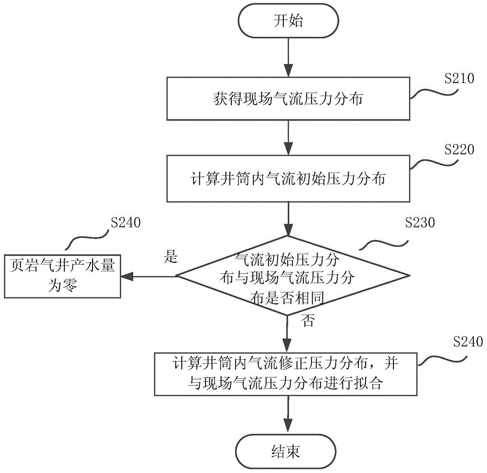
[0058] This embodiment provides a method for discriminating water production in shale gas wells and a method for predicting water production, which can be accurately calculated when the water production is extremely low.

[0059] Because the changes of fluid physical parameters in the wellbore are usually coupled, such as pressure, temperature, etc., which will affect each other, they cannot be calculated separately during the calculation process, and these parameters must be coupled and solved. The embodiment of the present invention is based on the theoretical results of expressions (1) and (2), adopts the method of calculating downwards from the wellhead, first divides the wellbore into sections, and then calculates section by section from the wellhead. The parameters of the upper outlet of each section are known, first assume a temperature value at the lower inlet, then use the pressure calculation model of the above expression (1) to calculate the lower inlet pressure, and...

Embodiment 2

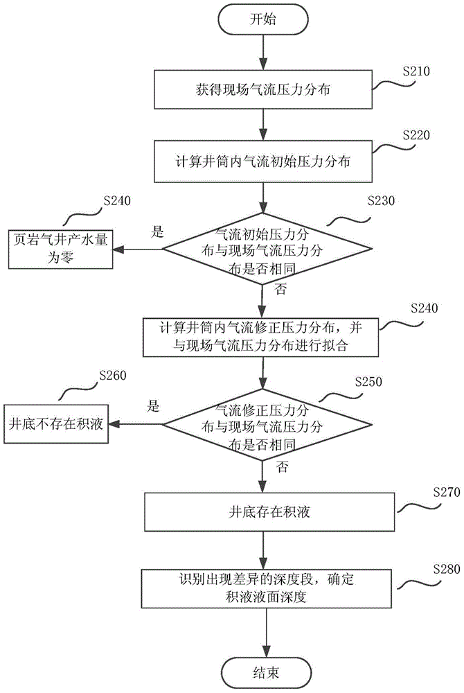
[0067] This embodiment provides a method for discriminating fluid accumulation at the bottom of a shale gas well and predicting the depth of fluid accumulation. Such as image 3 As shown, the method of this embodiment is based on the wellbore pressure fitting results of the first embodiment. exist image 3 The same steps are given the same reference numerals.

[0068] The difference from Example 1 is that in image 3 In the process, it also includes judging whether the calculated gas flow correction pressure distribution is the same as the on-site gas flow pressure distribution in the depth section near the bottom of the well (step S250), if they are the same, there is no liquid accumulation at the bottom of the well (step S260), if not If they are the same, there is fluid accumulation at the bottom of the well (step S270).

[0069] Further, if the calculated airflow correction pressure distribution is different from the on-site airflow pressure distribution in the depth s...

Embodiment 3

[0072] This embodiment provides a liquid drainage method for shale gas well bottomhole liquid accumulation, which can guide the site to take out the liquid accumulation by running oil pipes, prevent the gas well from shutting down due to excessive liquid accumulation, and improve the drainage efficiency of the shale gas well.

[0073] When it is judged that there is fluid accumulation at the bottom of the well, in order to discharge the fluid accumulation at the bottom of the well, it is necessary to run the tubing. Two parameters need to be determined when using the method of running the tubing, namely the running depth and the size of the tubing. This embodiment provides a method for determining the running depth of the oil pipe and the size of the oil pipe. The running depth of the tubing needs to be below the dynamic liquid level of the effusion, and the depth of the liquid level of the effusion can be obtained through the calculations in the examples, which is the minimum ...


PUM


Abstract

The invention discloses a determination method of producing water for a shale gas well, a determination method of accumulated liquid and a liquid drainage method.The determination method of producing water for the shale gas well comprises following steps: sampling pressure of airflows at different depths in a shaft on the construction site and obtaining on-site airflow pressure distribution; setting liquid-carrying quantities of airflows at different depths in the shaft as zero and calculating initial airflow pressure distribution in the shaft; comparing whether the initial airflow pressure distribution obtained by calculations is the same as the on-site airflow pressure distribution; determining the water-producing quantity in the shale gas well as zero if it is the same; and setting liquid-carrying quantities of airflows at different depths in the shaft if not, calculating the modified pressure distribution in the shaft, matching the modified airflow pressure distribution obtained by calculations with the on-site airflow pressure distribution and obtaining water producing quantity of the shale gas well. The determination method of producing water for the shale gas well, the determination method of accumulated liquid and the liquid drainage method have following beneficial effects: determinations can be made as to whether accumulated liquid exists in a well bottom of the shale gas well; the height of accumulated liquid in well bottom of the shale gas well can be calculated; and influence of accumulated liquid on production is analyzed.

Description

technical field [0001] The invention relates to the technical field of petroleum engineering, in particular to a method for determining water production in a shale gas well, a method for determining fluid accumulation and a fluid drainage method. Background technique [0002] As a clean energy, natural gas has a rapid growth in global consumption year by year. In 2013, my country's natural gas consumption reached 170 billion cubic meters. With the depletion of conventional natural gas resources in my country, large-scale development of unconventional natural gas resources is imperative. Shale gas is a typical unconventional natural gas resource extracted from shale formations. China is currently carrying out shale gas drilling and production in the Sichuan Basin, and has achieved good production. [0003] Due to the extremely low porosity and permeability of shale reservoirs, large-scale hydraulic fracturing must be used to form an artificial fracture network to produce g...

Claims


Application Information

Patent Timeline
IPC IPC(8): E21B47/10E21B47/06E21B43/00G06F19/00
Inventor 牛骏石在虹柯文奇苏建政张汝生张祖国王强唐萍王雅茹
Owner CHINA PETROLEUM & CHEM CORP
Why Eureka
Eureka Blog
Learn More