Cooling device of LED array device
A technology for LED arrays and cooling devices, which is applied in cooling/heating devices of lighting devices, lighting devices, semiconductor devices of light-emitting elements, etc., can solve problems such as increased manufacturing costs, poor heat dissipation efficiency, and increased costs, and achieve phase conversion Heat promotion, improved heat transfer efficiency, and easy maintenance
- Summary
- Abstract
- Description
- Claims
- Application Information
AI Technical Summary
Problems solved by technology
Method used
Image

Examples
Embodiment 1
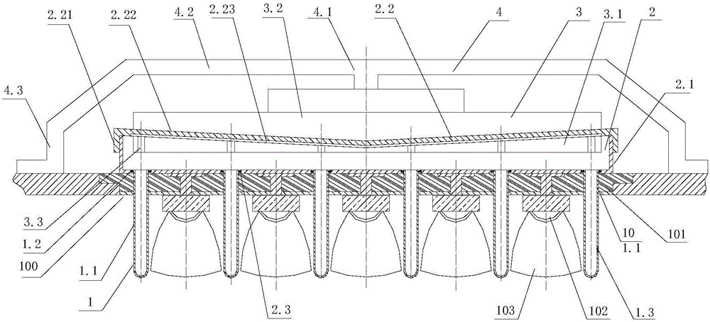
[0042] As shown in the figure, the LED array device 100 includes a substrate 101, and a plurality of LED light-emitting elements 102 are mounted on the substrate 100; a lens 103 is installed on each LED light-emitting element 102 to direct the light from the LED light-emitting element.
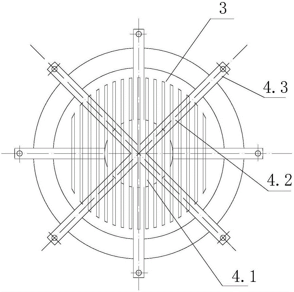
[0043] A cooling device for an LED array device, comprising a plurality of tubular evaporators 1, a condensation chamber 2, and a cooling fin 3; the condensation chamber 2 includes a cylindrical body 2.1 with an upper opening and a circular cover plate 2.2, the cover plate The 2.2 screw is fixed on the body 2.1. A plurality of mounting holes 2.3 are provided on the bottom plate of the body; the tube-shaped evaporator 1 is made of fast heat-conducting materials, such as copper, aluminum alloy or graphene or other materials with high thermal conductivity. The tubular evaporator 1 is installed on the installation hole 2.3 of the bottom plate of the condensation chamber 2; the tubular evaporator 1...
Embodiment 2
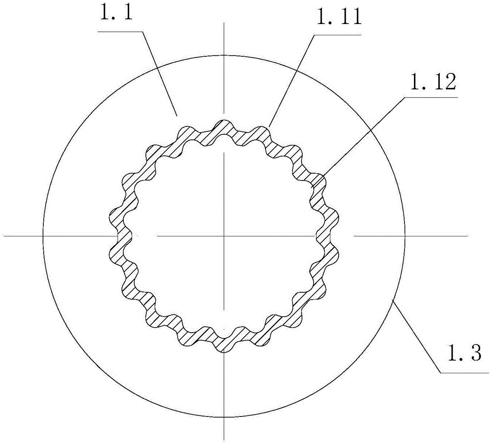
[0054] The tubular evaporator 1 includes a tube body 1.1, which is closed at both ends and contains a phase-change working medium; the condensation chamber 2 is filled with heat transfer oil, and the liquid surface of the heat transfer oil is at least in contact with the condensation of the heat dissipation disc 3 Section 3.1;
[0055] Other features are the same as in Example 1. The phase change heat dissipation in Example 2 occurs at the upper end of the tubular evaporator 1, the heat is transferred from the upper tube wall of the tubular evaporator 1 to the heat transfer oil, and the heat transfer oil is transferred to the heat dissipation fins, and the heat transfer medium of heat transfer oil is added in the middle , the phase change heat transfer increases the link, and reduces the efficiency of the phase change heat dissipation compared with Example 1.
[0056] The cooling device of the LED array device uses both conduction heat dissipation and phase change heat dissip...
PUM
 Abstract
Description
Claims
Application Information
 - R&D
- Intellectual Property
- Life Sciences
- Materials
- Tech Scout
- Unparalleled Data Quality
- Higher Quality Content
- 60% Fewer Hallucinations
Browse by: Latest US Patents, China's latest patents, Technical Efficacy Thesaurus, Application Domain, Technology Topic, Popular Technical Reports.
© 2025 PatSnap. All rights reserved.Legal|Privacy policy|Modern Slavery Act Transparency Statement|Sitemap|About US| Contact US: help@patsnap.com