An ultrasonic light hydrocarbon gas gas production process

An ultrasonic and gas technology, applied in the combustion method, liquid fuel supply/distribution, etc., can solve the problems of large space, large bulging power, and large overall volume of the gas generating tank, and achieve the effect of increasing the contact area.

Active Publication Date: 2018-07-10
SHANDONG UNIV OF TECH +1
View PDF6 Cites 0 Cited by
  • Summary
  • Abstract
  • Description
  • Claims
  • Application Information

AI Technical Summary

Problems solved by technology

As a result, the overall volume of the gas generating tank is large, takes up a large space, consumes a lot of blowing power, and the final gas production efficiency is low

Method used


Image

  • An ultrasonic light hydrocarbon gas gas production process

Examples


Embodiment 1

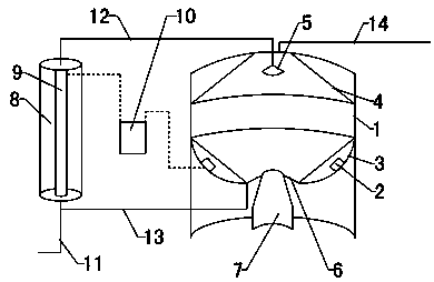
[0022] Adjust the oil spray head 5 on the top of the gas generating tank main body 1 to spray to form an oil mist, and simultaneously turn on the cyclone generator 7 to blow out the cyclone upwards, and the quality of the oil mist sprayed by the oil spray head 5 is the same as that of the air blown out by the cyclone generator 7. The mass ratio is 0.5:1; the ultrasonic distributor 3 emits ultrasonic waves with a frequency of 4300 HZ obliquely upwards. Under the action of ultrasonic waves, the oil mist is fully mixed with the gas in the cyclone, and the formed combustible gas is output from the gas outlet. Excessive oil mist It falls on the inclined ultrasonic distributor 3, is collected at the tank core, and is returned to the oil tank oil pipeline 11 by the oil return pipeline 13 for repeated use. The gas output by the gas pipeline 14 burns stably.

Embodiment 2

[0024] Adjust the oil spray head 5 on the top of the gas generating tank main body 1 to spray to form an oil mist, and simultaneously turn on the cyclone generator 7 to blow out the cyclone upwards, and the quality of the oil mist sprayed by the oil spray head 5 is the same as that of the air blown out by the cyclone generator 7. The mass ratio is 0.5:1; the ultrasonic distributor 3 emits ultrasonic waves with a frequency of 4200 HZ obliquely upwards, and the oil mist is fully mixed with the gas in the cyclone under the action of the ultrasonic waves, and the combustible gas formed is output from the gas outlet, and the excessive oil mist It falls on the inclined ultrasonic distributor 3, is collected at the tank core, and is returned to the oil tank oil pipeline 11 by the oil return pipeline 13 for repeated use. The gas output by the gas pipeline 14 burns stably.

Embodiment 3

[0026] Adjust the oil spray head 5 on the top of the gas generating tank main body 1 to spray to form an oil mist, and simultaneously turn on the cyclone generator 7 to blow out the cyclone upwards, and the quality of the oil mist sprayed by the oil spray head 5 is the same as that of the air blown out by the cyclone generator 7. The mass ratio is 0.4:1; the ultrasonic distributor 3 emits ultrasonic waves with a frequency of 4000 HZ obliquely upward, and the oil mist is fully mixed with the gas in the cyclone under the action of ultrasonic waves, and the combustible gas formed is output from the gas outlet, and the excessive oil mist It falls on the inclined ultrasonic distributor 3, is collected at the tank core, and is returned to the oil tank oil pipeline 11 by the oil return pipeline 13 for repeated use. The gas output by the gas pipeline 14 burns stably.


PUM


Abstract

An ultrasonic light hydrocarbon gas gas production process belongs to the technical field of gas preparation. It is characterized in that: the main body (1) of the gas generating tank is provided with an ultrasonic distributor (3), and the ultrasonic distributor (3) is provided with a first ultrasonic transducer (2) connected to the ultrasonic controller (10) , the central part of the lower part of the main body of the gas generating tank (1) is provided with a cyclone generator (7), the middle part of the ultrasonic distributor (3) surrounds the air outlet of the cyclone generator (7), and the main body of the gas generating tank (1) The top is provided with an oil spray head (5). On the basis of the existing bubbling gas production, this device completely changes the gas production form, adds an ultrasonic transducer device, and utilizes the mechanical vibration, cavitation and thermal effects of ultrasonic waves, so as to achieve a significant gasification effect on light hydrocarbon oil raw materials. Improve the overall performance of the device.

Description

technical field [0001] An ultrasonic light hydrocarbon gas gas production process belongs to the technical field of gas preparation. Background technique [0002] The light hydrocarbon gas generation system is a technology that uses petrochemical by-products and the residual liquid of liquefied petroleum gas as raw materials, and produces fuel gas through special equipment, which can realize the full utilization of existing energy. The existing fuel gas generators are all of the bubbling type, that is, air is blown into the gas generating tank, and the gas bubbles are naturally moved in the oil and mixed with light hydrocarbons to form combustible light hydrocarbon gas. In this way, in order to fully mix the air with the light hydrocarbons in the oil, the air needs to be blown into a certain depth, which requires a large depth of oil storage in the gas generating tank, and requires a relatively high pressure to blow the air in. As a result, the overall volume of the gas gen...

Claims


Application Information

Patent Timeline
Patent Type & Authority Patents(China)
IPC IPC(8): F23K5/22
CPCF23K5/22
Inventor 万隆巴奉军
Owner SHANDONG UNIV OF TECH
Why Eureka
Try Eureka