
Central air-conditioning chilled water system with intelligent layer control function

A chilled water system, layered control technology, applied in air conditioning systems, heating and ventilation control systems, heating and ventilation safety systems, etc., to achieve the effect of simplifying the overall structure, reducing noise, and reducing energy consumption

Pending Publication Date: 2017-02-15
GUANGDONG JINBEI ENERGY EFFICIENT TECH
View PDF0 Cites 6 Cited by
  • Summary
  • Abstract
  • Description
  • Claims
  • Application Information

AI Technical Summary

Problems solved by technology

[0005] The object of the present invention is to solve the shortcomings and deficiencies of the above-mentioned prior art, and provide a central air-conditioning chilled water system with intelligent layered control, which can control the layered delivery of chilled water by configuring separate cooling water supply pipes on each floor of a high-rise building , using the cooling method from top to bottom, the 10-12 ℃ chilled water produced by the refrigerator is delivered to the end of each room on each floor, and the layered sub-pumps are used for direct cooling, so that the temperature of the cold water pumped by each floor is the same, and the cooling Reasonable volume distribution, no uneven cooling in different processes, and reduced energy consumption and noise reduction

Method used


Image

  • Central air-conditioning chilled water system with intelligent layer control function
  • Central air-conditioning chilled water system with intelligent layer control function
  • Central air-conditioning chilled water system with intelligent layer control function

Examples


Embodiment Construction

[0036] see Figure 6 , the present invention provides a central air-conditioning chilled water system with intelligent hierarchical control, which includes a chilled water unit 1, a chilled water storage tank 2, a number of water supply pipes 3, and a number of groups for respectively being arranged on each floor of a multi-storey building Coil blower fan 4, and several water return pipes 5.

[0037] The chiller 1 is provided with a water inlet, a water outlet, a chilled water outlet and a return water inlet, and its internal structure is the same as that of the existing chiller 1, so it will not be repeated here. In the present invention, the water inlet and the water outlet of the chiller 1 are respectively connected to the water outlet and the water inlet of a cooling tower 6, and the chilled water outlet of the chiller 1 is connected to the chilled water storage tank The chilled water inlets of 2 are connected and connected.

[0038]The chilled water outlets of the chill...


PUM


Abstract

The invention relates to a central air-conditioning chilled water system with an intelligent layer control function. The central air-conditioning chilled water system comprises a water chilling unit, a chilled water storage tank, a plurality of water supply pipes, a plurality of coil fans arranged on all the storeys of a multi-storey building, and a plurality of water return pipes. Chilled water in the chilled water storage tank is input into the coil fans of all the storeys through the multiple water supply pipes which are used for supplying chilled water to all the storeys correspondingly and independently, and thus independent layer control of chilled water supply is achieved. Therefore, by arranging the independent chilled water supply pipes on each storey of the multi-storey building, layer control and chilled water conveying are conducted, the top-down cool supply mode is adopted, the chilled water at the temperature of 10-12 DEG C manufactured by a refrigerating machine is conveyed to the tail end of each room on each storey, and the effect that cooling capacity distribution of each storey is reasonable is achieved; the system structure is reasonable, a huge pipeline system is omitted, the pipe diameter is greatly decreased, the height of each storey is decreased, and the building cost is reduced; and in addition, the pipeline pressure is reduced, the overpressure risks of frozen pipelines are reduced, check valves are omitted so that resistance can be reduced, and the flow speed is decreased.

Description

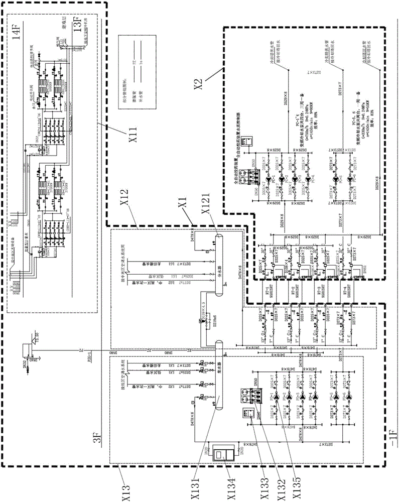
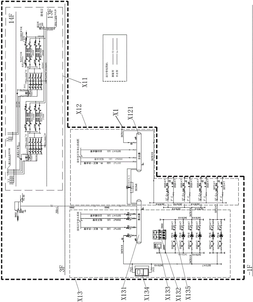
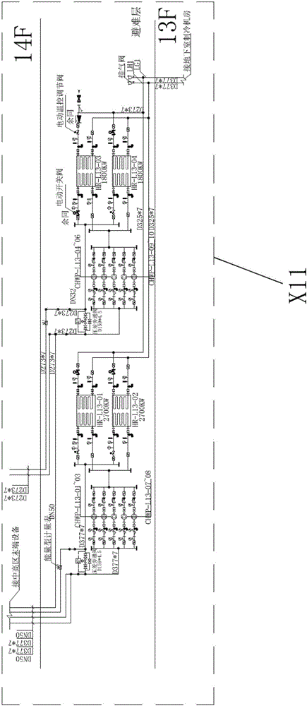
technical field [0001] The invention relates to an air-conditioning chilled water system, in particular to a central air-conditioning chilled water system with low energy consumption and low noise intelligent hierarchical control. Background technique [0002] The central air-conditioning cooling water system adopts single control to realize the function of circulating frozen water in summer and circulating hot water in winter. [0003] The existing central air-conditioning cooling water system has always used a large refrigeration pump, a large refrigeration pipeline system and a parallel structure of multiple refrigeration hosts, and is concentrated in a huge main pipe to realize the cooling of chilled water from bottom to top. see figure 1 , the existing central air-conditioning cooling water system includes a refrigeration system part X1 and a cooling system part X2. Among them, see figure 2 , the refrigeration system part X1 includes a mid-to-high zone plate convers...

Claims


Application Information

Patent Timeline
IPC IPC(8): F24F5/00F24F11/00F24F13/02
CPCF24F3/001F24F5/0017F24F11/70F24F11/84F24F13/0281Y02E60/14
Inventor 钱土
Owner GUANGDONG JINBEI ENERGY EFFICIENT TECH
Learn More