High-efficiency photoelectric conversion-based solar cell
A solar cell and solar cell technology, applied in the field of solar cells, can solve problems such as poor sealing and moisture resistance of solar cells, decreased stability, and reduced photoelectric conversion efficiency of solar cells, so as to improve photoelectric conversion efficiency and increase the probability of dye absorption. Effect of increasing photocurrent density
- Summary
- Abstract
- Description
- Claims
- Application Information
AI Technical Summary
Problems solved by technology
Method used
Image
Examples
Embodiment 1
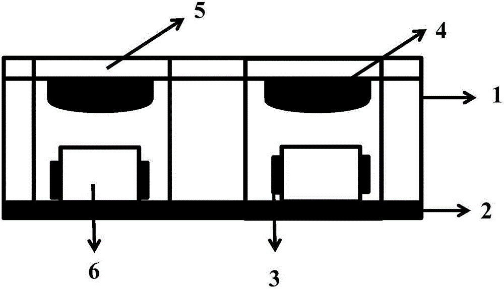
[0042] Depend on figure 1 , a solar cell based on high-efficiency photoelectric conversion, the solar cell includes: a base 1 , an electrode sheet 2 , a drying unit 3 , a focusing lens 4 , a glass substrate 5 and a solar cell unit 6 .
[0043] Preferably, the base 1 is provided with a groove structure, and the electrode sheet 2 is arranged at the bottom of the base 1 and contacts with the solar battery unit 6 .
[0044] Preferably, the electrode sheet 2 is a copper sheet.
[0045] Preferably, a focusing lens 4 is arranged on the top of the solar battery unit 6 , and a glass substrate 5 is mounted on the focusing lens 4 ; drying units 3 are arranged on both sides of the solar battery unit 6 .
[0046] Preferably, the solar cell unit 6 is based on a dye-sensitized solar cell, and the dye-sensitized solar cell is composed of a photoanode, a counter electrode and an electrolyte; the photoanode is sequentially composed of an FTO substrate, a transition layer, Tungsten trioxide se...
Embodiment 2
[0062] Depend on figure 1 , a solar cell based on high-efficiency photoelectric conversion, the solar cell includes: a base 1 , an electrode sheet 2 , a drying unit 3 , a focusing lens 4 , a glass substrate 5 and a solar cell unit 6 .
[0063] Preferably, the base 1 is provided with a groove structure, and the electrode sheet 2 is arranged at the bottom of the base 1 and contacts with the solar battery unit 6 .
[0064] Preferably, the electrode sheet 2 is a copper sheet.
[0065] Preferably, a focusing lens 4 is arranged on the top of the solar battery unit 6 , and a glass substrate 5 is mounted on the focusing lens 4 ; drying units 3 are arranged on both sides of the solar battery unit 6 .
[0066] Preferably, the solar cell unit 6 is based on a dye-sensitized solar cell, and the dye-sensitized solar cell is composed of a photoanode, a counter electrode and an electrolyte; the photoanode is sequentially composed of an FTO substrate, a transition layer, Tungsten trioxide se...
Embodiment 3
[0082] Depend on figure 1 , a solar cell based on high-efficiency photoelectric conversion, the solar cell includes: a base 1 , an electrode sheet 2 , a drying unit 3 , a focusing lens 4 , a glass substrate 5 and a solar cell unit 6 .
[0083] Preferably, the base 1 is provided with a groove structure, and the electrode sheet 2 is arranged at the bottom of the base 1 and contacts with the solar battery unit 6 .
[0084] Preferably, the electrode sheet 2 is a copper sheet.
[0085] Preferably, a focusing lens 4 is arranged on the top of the solar battery unit 6 , and a glass substrate 5 is mounted on the focusing lens 4 ; drying units 3 are arranged on both sides of the solar battery unit 6 .
[0086] Preferably, the solar cell unit 6 is based on a dye-sensitized solar cell, and the dye-sensitized solar cell is composed of a photoanode, a counter electrode and an electrolyte; the photoanode is sequentially composed of an FTO substrate, a transition layer, Tungsten trioxide se...
PUM
 Abstract
Description
Claims
Application Information
 - R&D
- Intellectual Property
- Life Sciences
- Materials
- Tech Scout
- Unparalleled Data Quality
- Higher Quality Content
- 60% Fewer Hallucinations
Browse by: Latest US Patents, China's latest patents, Technical Efficacy Thesaurus, Application Domain, Technology Topic, Popular Technical Reports.
© 2025 PatSnap. All rights reserved.Legal|Privacy policy|Modern Slavery Act Transparency Statement|Sitemap|About US| Contact US: help@patsnap.com


