Novel 3dB waveguide power divider

A power divider and waveguide technology, applied in the field of 3dB waveguide power divider, can solve the problems of difficult processing, complex structure, difficult application, etc., and achieve the effects of excellent electrical performance, high precision and simple processing

Inactive Publication Date: 2017-02-15
NO 54 INST OF CHINA ELECTRONICS SCI & TECH GRP
View PDF5 Cites 0 Cited by
  • Summary
  • Abstract
  • Description
  • Claims
  • Application Information

AI Technical Summary

Problems solved by technology

Moreover, the 3dB waveguide power splitters described in the two patents both use multi-stage waveguide matching sections, which are complex in structure and difficult to process, making it difficult to apply to millimeter wave frequency bands or multi-stage waveguide power splitting networks.

Method used


Image

  • Novel 3dB waveguide power divider
  • Novel 3dB waveguide power divider
  • Novel 3dB waveguide power divider

Examples


Embodiment Construction

[0020] The present invention will be described in further detail below in conjunction with the accompanying drawings.

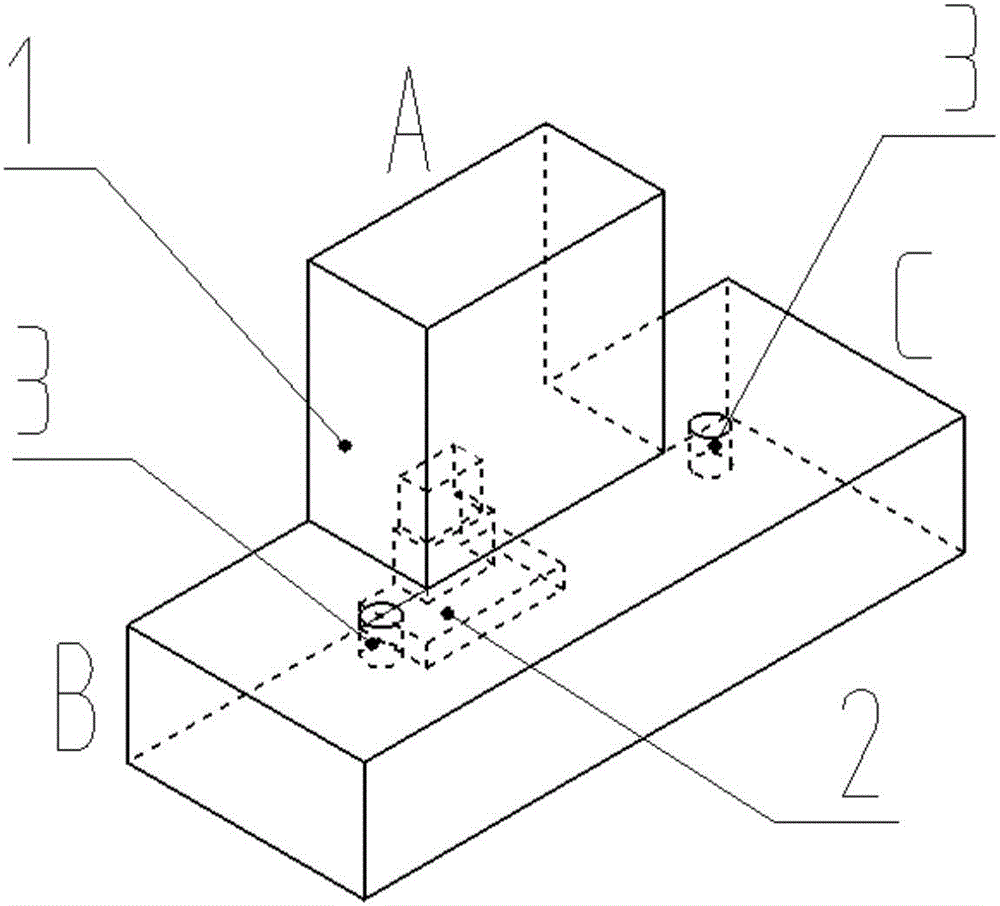
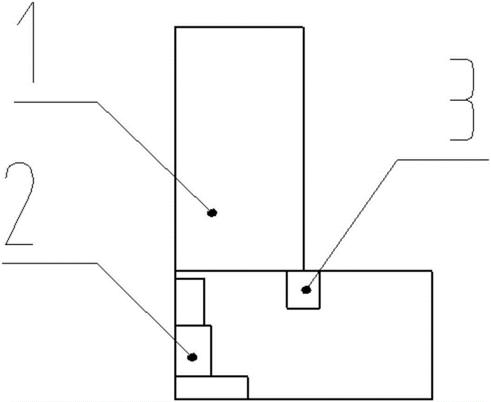
[0021] refer to figure 1 , a new type of 3dB waveguide power splitter, which consists of a T-shaped EH surface waveguide cavity 1, a stepped matching block 2 and two matching screws 3 to form a left-right symmetrical structure.

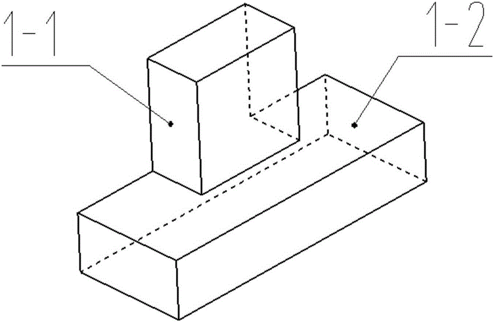
[0022] In the above structure, the T-shaped EH surface waveguide cavity 1 is composed of a common waveguide 1-1 and a power dividing waveguide 1-2, both of which are standard rectangles implementing the standard GB 11450.2-89 waveguide, port A is the common port, port B and port C are power split ports, and its connection structure is as follows figure 2 shown. The upper surface of the power dividing waveguide 1-2 is open, and the opening is greater than or equal to the port size of the common waveguide 1-1; one port of the common waveguide 1-1 is welded together with the upper surface opening of the power dividing waveguide 1-2 t...


PUM


Abstract

The present invention discloses a novel 3dB waveguide power divider and belongs to the microwave communication technical field. The 3dB waveguide power divider of the present invention comprises a T-shaped EH surface waveguide cavity, a stepped matching block and matching screws; two T-shaped standard rectangular waveguides are welded together so as to form the T-shaped EH surface waveguide cavity; the stepped matching block is located in the T-shaped EH surface waveguide cavity and includes three steps; and altogether 2 matching screws are adopted and are distributed at the inner wall of the T-shaped EH surface waveguide cavity in a mirror symmetry manner. The novel 3dB waveguide power divider of the invention is simple in structure and convenient to process. The standing waves of the ports of the novel 3dB waveguide power divider in frequency bands from 11.45GHz to 14.5GHz are smaller than 1.15; the phase and amplitude balance of the novel 3dB waveguide power divider are good; and the direction of the phase of the common port of the novel 3dB waveguide power divider is orthogonal to the directions of the electric fields of the two output ports of the novel 3dB waveguide power divider, and the directions of the electric fields of the two output ports of the novel 3dB waveguide power divider are identical. The novel 3dB waveguide power divider is suitable for being adopted as a power distribution or synthesis device of a broadband antenna and can be applied to conditions which have special requirements for the directions of the electric fields of ports.

Description

technical field [0001] The invention relates to a power divider in the technical field of microwave communication, in particular to a 3dB waveguide power divider. Background technique [0002] A power divider, referred to as a power divider, is an important component commonly used in microwave communication systems, and is used to realize the power distribution of one signal or the power combination of two signals. The electrical performance of the power splitter, such as operating bandwidth, port standing wave, isolation, phase and amplitude balance, etc., is of great significance to the entire microwave communication system. At present, the commonly used power dividers have two structural forms, microstrip and waveguide. In the occasions that emphasize low loss and high power, the waveguide structure is mostly used. 3dB waveguide power splitter is one of the simplest types of waveguide structure power splitters. In engineering, it is mostly used to realize equal-amplitude...

Claims


Application Information

Patent Timeline
Patent Type & Authority Applications(China)
IPC IPC(8): H01P5/12
CPCH01P5/12
Inventor 詹英武伟邹火儿
Owner NO 54 INST OF CHINA ELECTRONICS SCI & TECH GRP
Why Eureka
Try Eureka