Thermal isolation techniques

A heat and thermal barrier technology, applied in the direction of cooling/ventilation/heating transformation, modification through conduction heat transfer, climate sustainability, etc., can solve the problems of noisy cooling system, increasing the total energy consumption of the system, and increasing the cost of the system, etc. Achieve the effect of reducing thermal problems and increasing life

Active Publication Date: 2017-02-15
SANDISK TECH LLC
View PDF10 Cites 3 Cited by
  • Summary
  • Abstract
  • Description
  • Claims
  • Application Information

AI Technical Summary

Problems solved by technology

However, as mentioned above, these cooling systems are noisy; add significant expense to the system; increase the overall energy consumption of these systems; reduce the efficiency of the system, and do not always alleviate localized hot spots that form within the system

Method used


Image

  • Thermal isolation techniques
  • Thermal isolation techniques
  • Thermal isolation techniques

Examples


Embodiment Construction

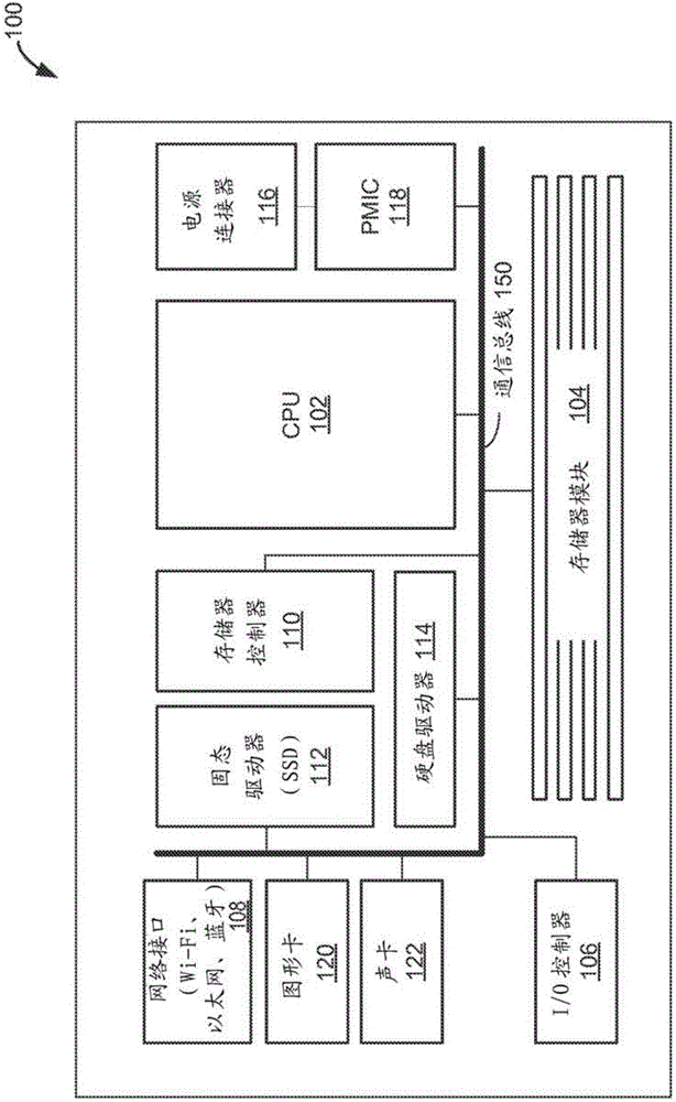
[0021] Various embodiments described herein include systems, methods, and / or devices for use by or integrated into electronic assemblies. In particular, the electronic systems, heat sinks, and methods of heat dissipation described herein facilitate the dissipation of heat generated by electronic components in the electronic system.

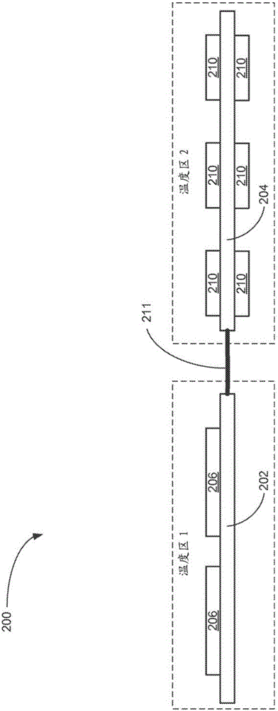
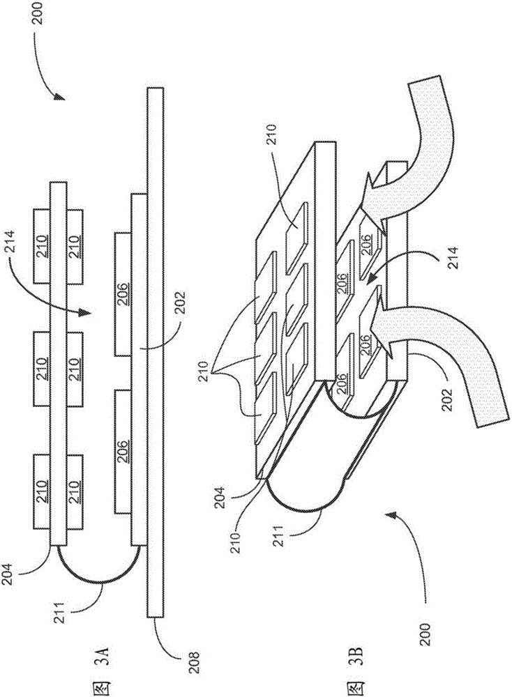
[0022] Embodiments described herein allow isolation of heat sensitive devices from heat generating devices on a PCBA (printed circuit board assembly). In some embodiments, the thermal barrier is formed by using a thermal barrier interconnect, such as a flex circuit board between two rigid printed circuit boards. This thermal barrier is used to allow one plate to operate at a lower temperature relative to the other plates. For example, a board with NAND flash may operate at a lower temperature relative to a board containing a NAND flash controller and power electronics. The difference in temperature between plates can be as high as 20 °C. This m...


PUM


Abstract

Various embodiments described herein include systems, methods and / or devices used to dissipate heat generated by electronic components in an electronic system (e.g., a memory system that includes closely spaced memory modules). In one aspect, an electronic assembly includes a first circuit board with one or more heat generating components coupled thereto. The electronic assembly further includes a second circuit board with one or more heat sensitive components coupled thereto. The electronic assembly also includes a thermal barrier interconnect. The thermal barrier interconnect electrically couples the first circuit board to the second circuit board. In some embodiments, thermal barrier interconnect is a flexible interconnect with a lower thermal conductivity than the first circuit board and the second circuit board. The thermal barrier interconnect forms a thermal barrier between the first and second circuit boards which protects the heat sensitive components from the heat generating components.

Description

technical field [0001] The disclosed embodiments relate generally to thermal management and, in particular, to dissipating heat generated by electronic components in electronic systems. Background technique [0002] Electronic devices, such as processors or memory, generate heat during operation. If left unchecked, this heat can degrade system performance and even cause partial or complete system failure. Accordingly, many existing techniques attempt to remove or dissipate heat through the use of heat sinks, cooling fans, and the like. [0003] While these techniques can be effective for cooling individual electronic components that are not located close to other heat sources, when it comes to more complex systems and higher density systems (such as solid-state drives (SSDs), dual in-line memory modules ( DIMM) and small DIMM packages, all of which use memory cells to store data as charge or voltage), these technologies fall short. [0004] Existing cooling systems for su...

Claims


Application Information

Patent Timeline
Patent Type & Authority Applications(China)
IPC IPC(8): G06F1/20
CPCG06F1/203H05K7/20518G06F1/20H05K7/20Y02D10/00
Inventor D.迪安R.W.埃利斯
Owner SANDISK TECH LLC
Why Eureka
Try Eureka