Copper brazing manufacturing method of fuel distribution pipe and radial connecting part of main pipe

A technology of radial connection and manufacturing method, which is applied in the direction of manufacturing tools, welding equipment, engine components, etc., can solve the problems of affecting the quality of welds, insufficient filling of internal gaps, and high energy, so as to ensure the consistency of weld quality and guarantee The effect of filling full and reducing production cost

Inactive Publication Date: 2017-02-22
UNITED AUTOMOTIVE ELECTRONICS SYST
View PDF6 Cites 6 Cited by
  • Summary
  • Abstract
  • Description
  • Claims
  • Application Information

AI Technical Summary

Problems solved by technology

In addition, the energy of argon arc welding or laser welding is high, so that the parts to be welded are connected through the melting of the material body, forming a large heat-affected zone at the welding point and reducing the strength of the material body; and the existence of the external tack welding spot 8 affects The continuity of the flow of copper glue 7 is not conducive to the formation of evenly transitioned rounded corners at the joints of the welds, resulting in stress concentration at 8 solder joints of tack welding, such as Figure 5 shown
[0010] 2) The copper glue 7 is coated on the outside of the joints of the parts, and penetrates from the outside to the inside under high temperature in the brazing furnace. It is impossible to 100% visually observe whether the copper glue 7 has penetrated the entire inner surface or filled the entire solder joint. There is a possibility that the internal gap filling is not full, which will affect the quality of the weld seam
However, due to the process of the casting itself, the surface of the parts is rough and uneven, which often causes the copper glue to flow and spread to the entire surface of the parts during the copper brazing process. Because copper is easily oxidized in the air to form a large amount of patina, affecting Product appearance, leading to customer complaints

Method used


Image

  • Copper brazing manufacturing method of fuel distribution pipe and radial connecting part of main pipe
  • Copper brazing manufacturing method of fuel distribution pipe and radial connecting part of main pipe
  • Copper brazing manufacturing method of fuel distribution pipe and radial connecting part of main pipe

Examples


Embodiment 1

[0061] Copper brazing manufacturing methods for fuel distribution pipes such as Figure 5 As shown, the fuel distribution pipe includes a main pipe 1, an axial connecting part of the main pipe, and a radial connecting part of the main pipe; the manufacturing process steps are as follows:

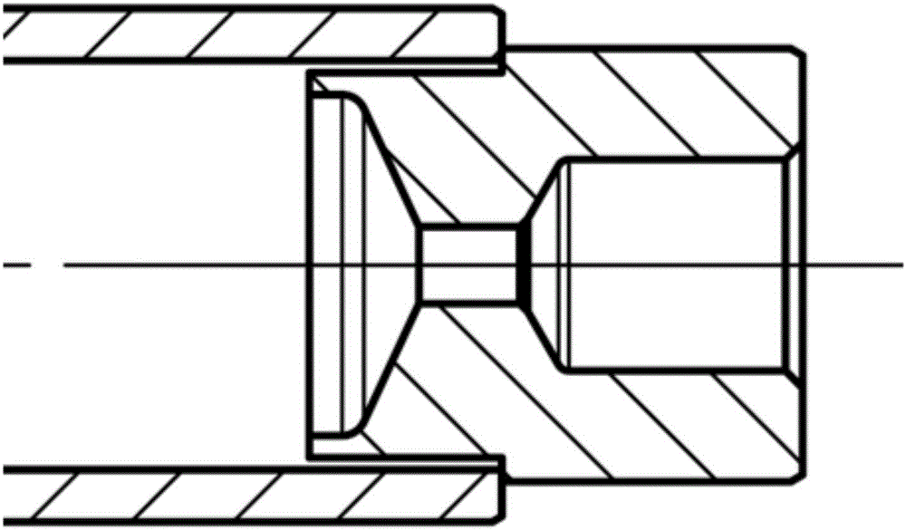
[0062] 1. If Figure 7 As shown, a copper ring 11 is built in the end of the main pipe 1 or a copper ring 11 is placed outside the axial connecting part of the main pipe, and then the axial connecting part of the main pipe is pressed and positioned on the end of the main pipe 1 in the axial direction, and the axial connecting part of the main pipe is connected with the The main pipes 1 are connected and fixed through partial interference fit, and the copper ring 11 is squeezed between the main pipe axial connection parts and the main pipe 1;

[0063] Such as Figure 8 , Figure 9 As shown, the radial connecting part of the main pipe has a circular arc fitting surface that matches the oute...

Embodiment 2

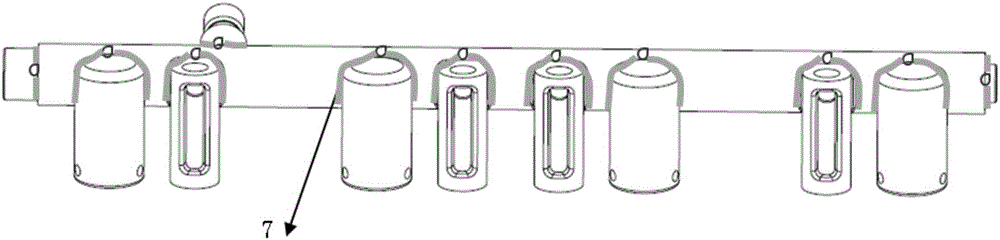
[0076] Based on the copper brazing manufacturing method of the fuel distribution pipe of embodiment 1, in step 2, a local brazing method is adopted, that is, the fuel distribution pipe does not enter the brazing furnace as a whole at the same time, but the axial connection parts of the main pipe, the radial direction of the main pipe Local brazing heating is carried out in batches and successively at the connection and fixing positions of the connecting parts and the main pipe.

[0077] The copper brazing manufacturing method of the fuel distribution pipe of the second embodiment adopts the local brazing method, and performs local heating in batches and sequentially at the joints of each part, so that the built-in copper ring or copper sheet melts at high temperature and penetrates from the inside to the outside to fill the entire weld. gap. According to the Hall-Page law, the smaller the grain size of the metal material, the higher the material strength. This process avoids t...

Embodiment 3

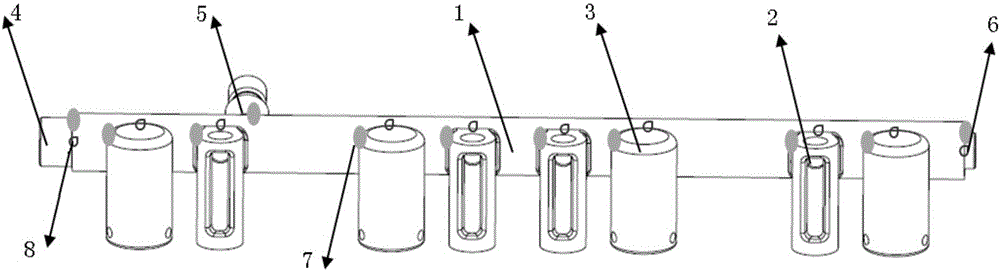
[0079] Based on the fuel oil distribution pipe copper brazing manufacturing method of embodiment two, such as Figure 6 As shown, the axial connecting parts of the main pipe are a sensor joint 4 and an end cover 6;

[0080] The radial connecting parts of the main pipe include a pipe joint 5, a bracket 2 and an injector seat 3;

[0081] In step 1, a copper ring is built into the end of the main pipe or a copper ring 11 is placed outside the sensor connector 4 and the end cap 6, and then the sensor connector 4 and the end cap 6 are pressed and positioned on both ends of the main pipe 1 along the axial direction, and the sensor connector 4 and the end cover 6 and the main pipe 1 are connected and fixed through partial interference fit, and the copper ring 11 is squeezed between the sensor joint 4 or the end cover 6 and the main pipe 1;

[0082] The pipe joint 5, the bracket 2 and the fuel injector seat 3 each have an arc fitting surface matching the outer wall of the main pipe 1...


PUM


Abstract

The invention discloses a copper brazing manufacturing method of a fuel distribution pipe. The method is characterized in that press fitting and projection welding, instead of argon-arc welding or laser welding, are carried out to position, so that the uniformity of welding gaps among parts can be effectively improved, and the consistency of the quality of the welding gaps formed after the copper brazing can be ensured; a built-in copper ring or copper sheet is used and replaces externally-paved copper adhesive, so that copper can permeate from inside to outside during the copper brazing process, and as a result, the welding gaps can be fully filled with the copper adhesive; in addition, the flowing conidtio of the copper adhesive in the welding gaps can be inspected through the appearance rather than a destructive way, so that he production cost can be reduced. The invention discloses a radial connecting part of the main pipe.

Description

technical field [0001] The invention relates to mechanical processing and manufacturing technology, in particular to a copper brazing manufacturing method of a fuel distribution pipe and a radial connecting part of a main pipe. Background technique [0002] High-pressure fuel distribution pipes are widely used in direct injection engines to store and distribute high-pressure fuel. Such as figure 1 , figure 2 As shown, the high-pressure fuel distribution pipe is generally composed of a main pipe 1, a bracket 2, an injector seat 3, a sensor joint 4, a pipe joint 5 and an end cover 6. [0003] Brazing is to use a metal material with a lower melting point than the base metal as the solder, heat the weldment and the solder to a temperature higher than the melting point of the solder and lower than the melting temperature of the base metal, use liquid solder to wet the base metal, fill the gap between the joints and The method of interdiffusion with the base metal to realize t...

Claims


Application Information

Patent Timeline
Patent Type & Authority Applications(China)
IPC IPC(8): B23K1/008B23K1/20F02M55/00
CPCB23K1/0008B23K1/008B23K1/20F02M55/008
Inventor 张满意
Owner UNITED AUTOMOTIVE ELECTRONICS SYST
Why Eureka
Try Eureka