Complex structural well friction resistance reduction and power drill tool face adjusting method

A dynamic drilling tool and complex structure technology, applied in drilling equipment and methods, automatic drilling control systems, drill pipes, etc., can solve problems such as reducing the effect of friction reduction, difficulty in implementation, and inability to accurately judge the corresponding relationship between ground torsion

Inactive Publication Date: 2017-02-22
CHINA UNIV OF PETROLEUM (EAST CHINA)
View PDF12 Cites 30 Cited by
  • Summary
  • Abstract
  • Description
  • Claims
  • Application Information

AI Technical Summary

Problems solved by technology

Although the above method can achieve a certain effect of reducing friction, it also has defects, which are mainly reflected in two aspects. One is to avoid the ground torsion effect from affecting the stability of the tool face angle of the power drilling tool. In the buffer zone, the drill string does not rotate, thereby reducing the friction reduction effect; second, when the horizontal extension distance of the well is long, only when the ground torsion depth is relatively large in a torsional pendulum cycle In order to have an obvious anti-friction effect; the patent U.S.Pat No. 7,588,100 has announced a method for reducing friction in complex structure wells with variable speed drilling. The

Method used


Image

  • Complex structural well friction resistance reduction and power drill tool face adjusting method
  • Complex structural well friction resistance reduction and power drill tool face adjusting method
  • Complex structural well friction resistance reduction and power drill tool face adjusting method

Examples


Embodiment

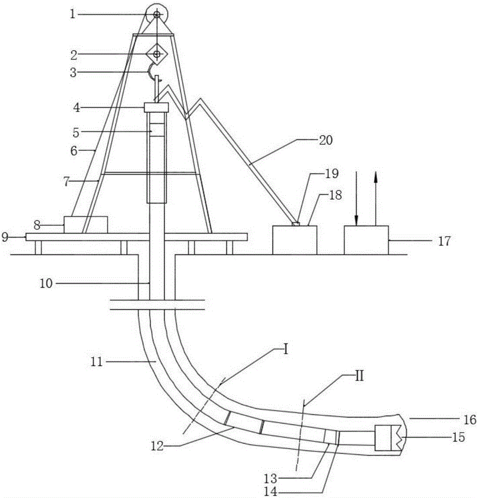
[0030] This embodiment is realized in the friction reduction and power drilling tool face adjustment device for wells with complex structures, and the specific process is as follows:

[0031] (1) After sliding drilling in directional wells to a certain well depth, since the drill string 10 lying on the lower side of the wellbore 11 is longer and has greater frictional resistance, the mechanical penetration rate of sliding drilling is relatively slow, for example, less than 1m / hour. Pull out the drill and access the axial vibration drag reduction tool 12; measure the load value and ground torque value of the hook 3 under the three working conditions of the drill bit rotating from the bottom, lifting the drill string and lowering the drill string, and the time when the drill is rotating from the bottom. The standpipe pressure value P off , and then use the "soft model" calculated by the frictional torque proposed in the document "Torque and Drag in Directional Wells-Prediction a...


PUM


Abstract

The invention belongs to the technical field of well drilling, and relates to a complex structural well friction resistance reduction and power drill tool face adjusting method. A whole originally pure sliding drilling string is divided into three portions, the upper portion of the drilling string rotates in a reciprocating manner under the action of torque applied by a surface well drilling top drive, the middle of the drilling string axially vibrates/creeps under the action of an axial vibration resistance reduction tool, and static friction between the drilling string and a well wall is transformed into dynamic friction, so that axial feeding resistance of the drilling string is reduced. A drill bit on the lower portion of the drilling string can axially vibrates, so that bit pressure fluctuates, rock breaking torque and reaction torque fluctuate, the fluctuating reaction torque acts on the lower portion of the drilling string close to the drill bit, the lower portion of the drilling string rotates in a reciprocating manner, and friction resistance can be reduced. The method is convenient in operation and scientific in principle, power drill tool face adjusting time can be saved, drilling is continued while a tool face is adjusted, the drilling efficiency of a complex structural well, particularly the complex structural well with long horizontal displacement is improved, and well drilling cost is reduced.

Description

[0001] Technical field: [0002] The invention belongs to the technical field of drilling, and relates to a friction reduction and power drilling tool face adjustment process in the sliding drilling process of complex structure wells, in particular to a friction reduction and power drilling tool face adjustment method for complex structure wells. [0003] Background technique: [0004] Compared with ordinary vertical wells, wells with complex structures such as horizontal wells have a larger reservoir control area, which can greatly increase the production of a single well and reduce the cost per ton of oil. It has become the most important means of developing complex oil and gas reservoirs and offshore oil and gas resources. At present, the traditional directional drilling method of "dynamic drilling tool + MWD" is still widely used in the drilling of complex structure wells. In the process of directional drilling, there is a lot of friction between the drill string and the wel...

Claims


Application Information

Patent Timeline
IPC IPC(8): E21B7/04E21B7/24E21B17/07E21B44/00E21B44/04E21B21/08
CPCE21B7/04E21B7/046E21B7/24E21B17/076E21B21/08E21B44/00E21B44/04
Inventor 倪红坚王学迎王瑞和
Owner CHINA UNIV OF PETROLEUM (EAST CHINA)
Why Eureka
Try Eureka