Valve motion measurement assembly for an internal combustion engine

An internal combustion engine, motion measurement technology, applied in the direction of engine testing, engine components, internal combustion engine testing, etc., can solve problems such as sensor damage, unreliability, and difficulty in interpreting sensor output.

Inactive Publication Date: 2017-02-22
GM GLOBAL TECH OPERATIONS LLC
View PDF6 Cites 1 Cited by
  • Summary
  • Abstract
  • Description
  • Claims
  • Application Information

AI Technical Summary

Problems solved by technology

Also, the sensor can be damaged due to too high temperature during combustion
[0005] With this proximity, testing in the absence of combustion does not provide a detailed picture of actual engine valvetrain performance, particularly valve opening a

Method used


Image

  • Valve motion measurement assembly for an internal combustion engine
  • Valve motion measurement assembly for an internal combustion engine
  • Valve motion measurement assembly for an internal combustion engine

Examples


Embodiment Construction

[0036] The following detailed description is exemplary only and is not intended to limit the invention or the application and uses of the invention. Furthermore, there is no intention to be bound by any theory presented in the preceding background of the invention or the following detailed description.

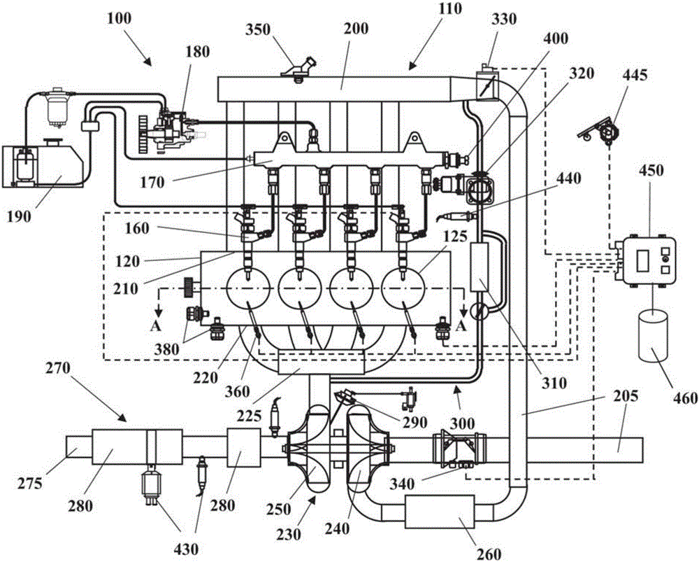
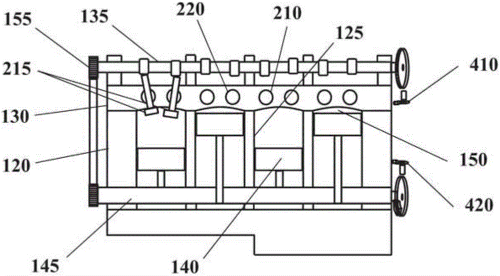
[0037] Some embodiments may include automotive systems 100 such as figure 1 and 2As shown, it includes an internal combustion engine (ICE) 110 having an engine block 120 defining at least one cylinder 125 having a piston 140 coupled to rotate a crankshaft 145 . Cylinder head 130 cooperates with piston 140 to define combustion chamber 150 . A fuel and air mixture (not shown) is disposed in combustion chamber 150 and ignited, the resulting thermally expanding exhaust causes reciprocating motion of piston 140 . Fuel is provided through at least one fuel injector 160 and air is provided through at least one air intake 210 . Fuel injector 160 is supplied fuel at high pressure f...


PUM


Abstract

A valve motion measurement assembly is provided for a cylinder valve of an internal combustion engine provided with a valve stem and with a valve head. The valve motion measurement assembly includes a valve position sensor, a supporting bracket provided with at least one sensor seat for the valve position sensor, and a sensor target element configured to be coupled to the valve stem at a distance from the valve head to follow the motion of the cylinder valve. The valve position sensor interacts with the sensor target element for determining the position of the cylinder valve.

Description

technical field [0001] The present invention relates to the measurement of valve movement of internal combustion engines, and in particular to the measurement of the movement (ie lift) of cylinder valves of internal combustion engines, ie valves allowing exhaust and intake air from the cylinders. Background technique [0002] Valve movement measurements are typically performed during engine testing, but for applications with variable valve opening systems a series of devices for continuous valve lift monitoring would be required. Typically, a sensor (usually a proximity or laser sensor) is directed towards the valve head to measure the valve's movement. However, to mount these sensors, holes should be machined into the cylinder head to locate the sensor support elements. This is a long, complex and expensive process. Furthermore, in typical valve motion measurements for development purposes, the sensor is towards the upper part of the valve head, which is filtered. Becaus...

Claims


Application Information

Patent Timeline
IPC IPC(8): F01L3/24
CPCF01L3/24F01L2820/045F01L1/46F02B77/082G01B21/16G01M15/00G01M15/02G01M15/04G01M15/042F01L2820/04F01L2820/041
Inventor A.库蒂亚尔L.特拉布基A.科尔特拉
Owner GM GLOBAL TECH OPERATIONS LLC
Why Eureka
Try Eureka