Eureka AIR delivers breakthrough ideas for toughest innovation challenges, trusted by R&D personnel around the world.

Method of operating an internal combustion engine

A technology for internal combustion engines and computer programs, applied in the direction of internal combustion piston engines, combustion engines, engine control, etc., can solve the problems of increasing regeneration duration or frequency, unstable temperature, temperature instability, etc., to improve oil life, improve Effect of temperature control, oil dilution reduction

Active Publication Date: 2017-02-22
GM GLOBAL TECH OPERATIONS LLC
View PDF4 Cites 4 Cited by
  • Summary
  • Abstract
  • Description
  • Claims
  • Application Information

AI Technical Summary

Problems solved by technology

[0008] Another issue is the reduced efficiency of aftertreatment processes such as DPF regeneration or LNT desulfurization due to temperature instability in customer real driving conditions, resulting in high unburned soot residue or low sulfur removal at the end of the regeneration process
This means that increased regeneration duration or frequency is bad for fuel economy due to more regenerations experienced over the life of the component, degraded system performance due to thermal stress or aging due to increased exposure to the high temperatures reached during the regeneration process (oxidizing capacity), potentially detrimental to emissions
Additionally, a high degree of calibration work on the post injection control may be required to allow for a sufficiently stable upstream aftertreatment system temperature in each driving condition
[0009] Finally, the urban cycle is one of the most critical situations for the effectiveness of the regeneration process under the conditions of actual customer driving: frequent operation with acceleration, deceleration and engine idling at lower engine speeds and loads, resulting in Highly variable and unstable temperatures and consequently very complex control of post-injection to ensure desired temperatures are achieved

Method used


Image

  • Method of operating an internal combustion engine
  • Method of operating an internal combustion engine
  • Method of operating an internal combustion engine

Examples


Embodiment Construction

[0026] The following detailed description is exemplary only and is not intended to limit the invention or the application and uses of the invention. Furthermore, there is no intention to be bound by any theory presented in the preceding background of the invention or the following detailed description.

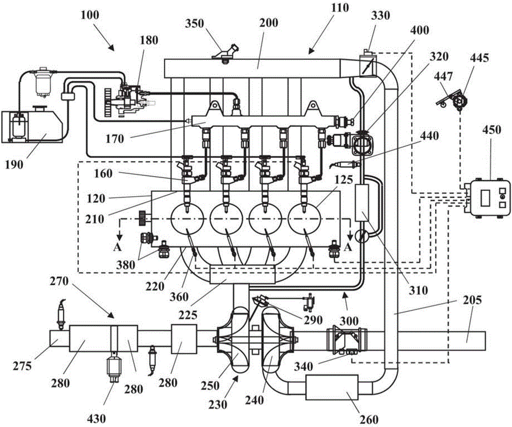
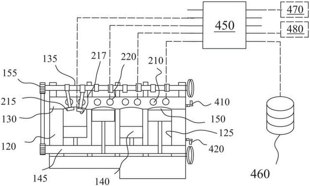
[0027] Some embodiments may include such as figure 1 with 2 The illustrated automotive system 100 includes an internal combustion engine (ICE) 110 having an engine block 120 defining at least one cylinder 125 having a piston 140 coupled to rotate a crankshaft 145 . Cylinder head 130 cooperates with piston 140 to define combustion chamber 150 . A fuel and air mixture (not shown) is placed in combustion chamber 150 and ignited, resulting in thermally expanding exhaust gases that cause reciprocation of piston 140 . Fuel is provided by at least one fuel injector 160 and air passes through at least one intake port 210 . Fuel is provided to fuel injector 160 at high pressure fro...


PUM


Abstract

A method is disclosed for operating an internal combustion engine equipped with an aftertreatment device. The internal combustion engine is equipped with a cylinder having an exhaust gas port intercepted by an exhaust valve, the exhaust valve being actuated by means of a Variable Valve Actuation (VVA) system, An aftertreatment device regeneration is detected, and the exhaust valve closure is anticipated using the Variable Valve Actuation (VVA) system during the aftertreatment device regeneration to provide an exhaust valve actuation profile having an anticipated exhaust valve closure with respect to a baseline exhaust valve actuation profile.

Description

technical field [0001] The invention relates to a method of operating an internal combustion engine. Background technique [0002] Due to continuously stricter emission requirements, internal combustion engines are equipped with aftertreatment exhaust systems such as diesel oxidation catalysts (DOC), diesel particulate filters (DPF), lean NOx adsorption technology (LNT) and / or selective catalytic reduction (SCR) system or SCRF (SCR on filter), etc., the conversion efficiency is strictly related to the exhaust gas temperature. Carbon dioxide levels mandated by future legislation will drive to lower temperatures within the exhaust pipe, creating critical operating conditions that may affect the ability of the aftertreatment system to operate at optimum efficiency. [0003] Several valve control technologies have been developed; one of them is variable valve actuation (VVA), which allows an optimized cam profile for intake and / or exhaust valves in terms of valve timing or lift...

Claims


Application Information

Patent Timeline
Patent Type & Authority Applications(China)
IPC IPC(8): F02D13/02
CPCF02D13/0249F02D41/0245F02D41/027F02D2041/001F02D2200/08Y02T10/12F02D13/02F02D13/0242F02D41/02F02D41/021F02D41/0235
Inventor A.莫加沃罗A.拉卡J.德拉莫雷纳
Owner GM GLOBAL TECH OPERATIONS LLC
Why Eureka
Eureka Blog
Learn More