Working condition control device in pump turbine speed adjusting system and control method of working condition control device

A technology of water pump turbine and speed control system, which is applied in the direction of speed control, safety device, control system use, etc., can solve the problems of insufficient protection of units and equipment, limited operating range and operating interval of units, and easily damaged equipment, etc., and achieves a simple structure. , low cost, the effect of expanding the operating range and scope

Active Publication Date: 2017-02-22
QINGYUAN PUMPED STORAGE POWER GENERATION CO LTD +1
View PDF5 Cites 8 Cited by
  • Summary
  • Abstract
  • Description
  • Claims
  • Application Information

AI Technical Summary

Problems solved by technology

[0003] In the existing technology, the speed control system of the pump turbine only calculates the corresponding guide vane closing law according to the worst working condition, and then uses this guide vane closing law to control regardless of the working condition. This scheme, in the same Under the design conditions of the waterway, the operating range and operating range of the unit are limited, the protection of the unit and equipment is insufficient, and the equipment is easily damaged

Method used


Image

  • Working condition control device in pump turbine speed adjusting system and control method of working condition control device
  • Working condition control device in pump turbine speed adjusting system and control method of working condition control device
  • Working condition control device in pump turbine speed adjusting system and control method of working condition control device

Examples


Embodiment 1

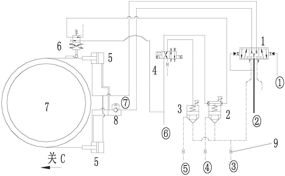
[0037] see figure 1 , the operating condition control device in the speed regulating system of the water pump and turbine in this embodiment includes a main pressure distribution valve 1, a shuttle valve cartridge valve group 2, a cartridge valve 3, a working condition selection valve 4, a servomotor 5, and a segmented closing valve group 6. Guide vane control ring 7, check valve 8, electro-hydraulic control oil input port ①, pressure oil input port ②, 3 throttle oil discharge ports (the first throttle oil discharge port ③, the second throttle oil discharge port Port ④, third throttle oil discharge port ⑤), control oil input port ⑥, throttle valve ⑦. According to the figure, the following describes the connection relationship of each component as follows.

[0038] The input end of the main pressure distribution valve 1 is respectively connected to the electro-hydraulic control oil input port ① and the pressure oil input port ② through pipelines, and the output end is respecti...


PUM


Abstract

The invention discloses a working condition control device in a pump turbine speed adjusting system and a control method of the working condition control device. The device comprises a main distributing valve, a shuttle valve cartridge valve set, a cartridge valve, a working condition selecting valve, a servomotor, a sequence closing valve set, a guide vane control ring, a check valve, an electro-hydraulic control oil input port, a pressure oil input port, three throttling oil discharging ports, a control oil input port and a throttle valve. Selection of working conditions is conducted through the working condition selecting valve, and then when load shedding is conducted under the situation that a pump turbine unit breaks down, sequence closing of guide vanes under the working condition is achieved through cooperation of the main distributing valve, the shuttle valve cartridge valve set, the cartridge valve and the like. According to the working condition control device and the control method, the working condition selecting valve and the shuttle valve cartridge valve set are additionally arranged in the device creatively, different closing rules of the same device under different working conditions are achieved, rising of the load shedding pressure of the unit under multiple working conditions is reduced, and the running section and range of the unit are enlarged; and protection on the unit is reliably improved, and the beneficial effects that the structure is simple, cost is low and control is accurate are achieved.

Description

technical field [0001] The invention belongs to the technical field of hydroelectric power generation, and in particular relates to a working condition control device and a control method thereof in a speed regulating system of a pump turbine. Background technique [0002] At present, in order to ensure that the speed increase rate and maximum pressure increase rate of the large-scale pump turbine are within the specified range during the load shedding process, and to ensure the safety of the waterway of the unit, it is necessary to calculate the optimal closing time of the guide vane to ensure the safe operation of the unit . After the optimal closing time of the guide vane is calculated, the guide vane closing curve of the pump-turbine needs to follow the established guide vane closing law. Since the realization of this curve needs to be realized by mechanical equipment, and at the same time, it is necessary to realize the two rotation directions of the pump turbine while...

Claims


Application Information

Patent Timeline
Patent Type & Authority Applications(China)
IPC IPC(8): F03B15/00
CPCF03B15/00F05B2270/1014Y02E10/20
Inventor 汪志强吕志鹏季怀杰陈泓宇刘鸿祥宋继南闫双键何伟晶赵溢丰
Owner QINGYUAN PUMPED STORAGE POWER GENERATION CO LTD
Why Eureka
Try Eureka