
A staggered bed drying device

A technology of drying device and fixed bed, which is applied in the direction of drying, dryer, drying gas arrangement, etc. It can solve the problems of low thermal efficiency, large power consumption, and small production capacity of a single machine, and achieve the effect of high thermal efficiency and low noise

Active Publication Date: 2019-03-15
BEIJING JUXING NEW ENERGY TECH CO LTD
View PDF5 Cites 0 Cited by
  • Summary
  • Abstract
  • Description
  • Claims
  • Application Information

AI Technical Summary

Problems solved by technology

[0002] At present, there are several drying methods for granular materials and powders, and there are disadvantages at the same time. Rotary kiln, box kiln, and fluidized bed drying are only suitable for granular materials, and the thermal efficiency is low, generally around 30%. Fluidized bed drying The thermal efficiency is slightly higher, but the power consumption is large, and the drying cost is high; airflow drying and flash drying are more suitable for powder materials. The advantage is that the thermal efficiency is about 50% higher, and the single-machine capacity is large. However, the subsequent product collection The equipment is complicated, the evaporation capacity is 3 tons per hour, the induced draft fan motor is 350 kilowatts, the power consumption is high, the investment is large, the production environment is dusty, the product moisture cannot be adjusted, and the drying cost is high; rake drying, vertical disc drying, It is suitable for powder, and the moisture content of the product can be adjusted. It is heat-exchanged and dried by conduction. Only the material can be heated when it touches the disc. The thermal efficiency is low. The heat source uses steam 1500C or heat-conducting oil. The dryer becomes a pressure vessel, which has potential safety hazards. The cost of the dryer is high, the biggest problem is that the capacity of a single machine is too small, and the maximum hourly evaporation of a single machine is 0.9 tons

Method used


Image

  • A staggered bed drying device
  • A staggered bed drying device
  • A staggered bed drying device

Examples


Embodiment Construction

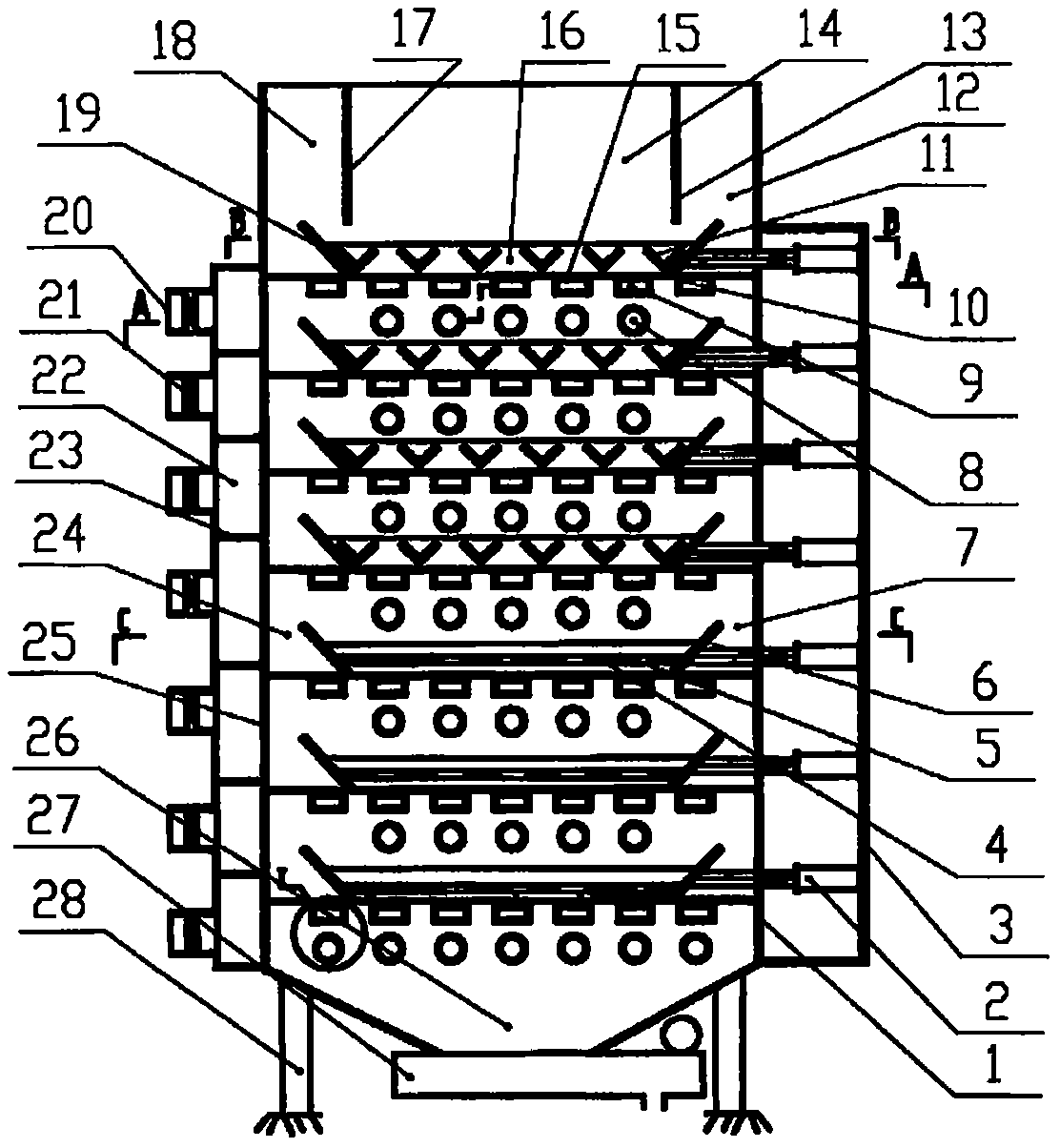
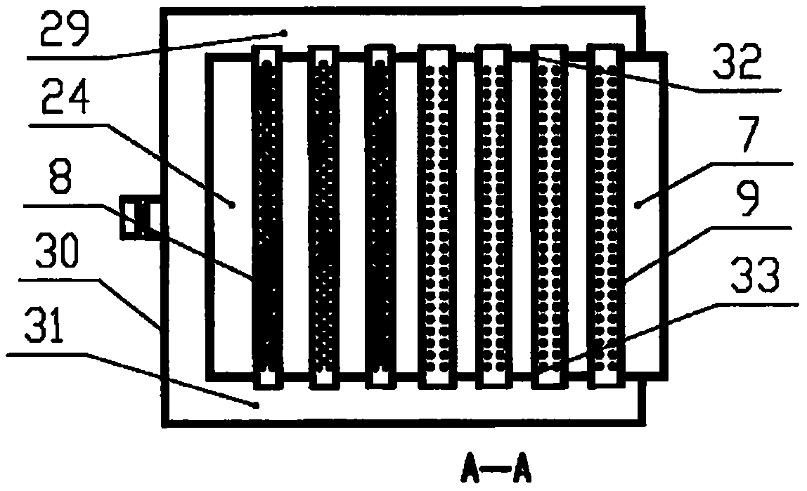
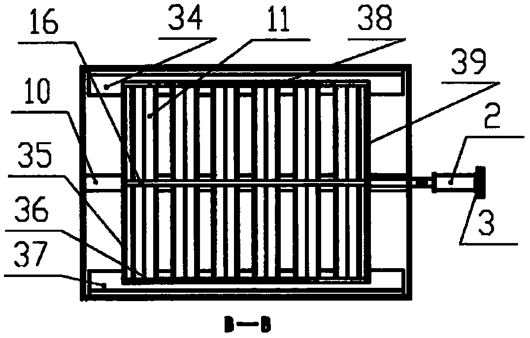
[0025] Such as Figure 1 to Figure 4 A staggered bed drying device shown is composed of a main body front plate 25, a main body rear plate 1, a main body left plate 33, and a main body right plate 32 to form a vertical rectangular box main body supported by legs 28; the upper part of the main body is provided with The silo 14, the front moisture outlet 18, and the rear moisture outlet 12 are surrounded by the silo rear plate 13, the silo front plate 17, the main body right plate 32, and the main body left plate 33; the finished product hopper 26 and the conveyor 27 are arranged at the lower part of the main body; The side of the main body is provided with a multi-layered hot air channel 22 from top to bottom, a left hot air header 31, a right hot air header 29 and a hot air inlet 20; The bed 19 is connected to the oil hydraulic cylinder transmission assembly 2 of the slab movable bed 6 .

[0026] The main body is provided with multi-level layers consisting of angle steel 11, ...


PUM


Abstract

The invention discloses a staggered bed drying device and method. A casing is a vertical type rectangular box; a stock bin and moisture outlets are formed in the upper portion of the casing; a finished product conveying device is arranged at the lower portion of the casing; multiple layers of staggered beds are arranged inside the box; a material falls on the staggered beds from the stock bin; cylinder sets drives movable beds to reciprocate; the material on fixed beds is scraped and conveyed onto the next group of fixed beds; hot air enters hot air circular pipes with three rows of holes and fixed bed square pipes with two rows of holes; then the hot air is sprayed onto the material uniformly, and direct drying is carried out; moisture produced by drying passes through empty-layer channels located below square pipe fixed beds and above the hot air circular pipes, flows towards the front side and the back side of each channel into moisture channels and is exhausted out of the moisture outlets; when the material reaches the moisture content which should be lost in the current layer, the material is conveyed to the next stage of staggered beds and dried continuously; and the same operation is repeated till the material is dried to reach the required moisture content.

Description

technical field [0001] The invention relates to a staggered bed drying device, which belongs to the technical field of material drying. Background technique [0002] At present, there are several drying methods for granular materials and powders, and there are disadvantages at the same time. Rotary kiln, box kiln, and fluidized bed drying are only suitable for granular materials, and the thermal efficiency is low, generally around 30%. Fluidized bed drying The thermal efficiency is slightly higher, but the power consumption is large, and the drying cost is high; airflow drying and flash drying are more suitable for powder materials. The advantage is that the thermal efficiency is about 50% higher, and the single-machine capacity is large. However, the subsequent product collection The equipment is complicated, the evaporation capacity is 3 tons per hour, the induced draft fan motor is 350 kilowatts, the power consumption is high, the investment is large, the production envir...

Claims


Application Information

Patent Timeline
Patent Type & Authority Patents(China)
IPC IPC(8): F26B17/26F26B21/00
CPCF26B17/16F26B17/26F26B21/003F26B2200/08
Inventor 舒瑞舒克孝
Owner BEIJING JUXING NEW ENERGY TECH CO LTD
Features
  • Generate Ideas
  • Intellectual Property
  • Life Sciences
  • Materials
  • Tech Scout
  • Unparalleled Data Quality
  • Higher Quality Content
  • 60% Fewer Hallucinations
Learn More