Supercharge Your Innovation With Domain-Expert AI Agents!

Shaped capillary channel heat exchanger

A heat exchanger and capillary technology, applied in indirect heat exchangers, heat exchanger types, heat exchange equipment, etc., can solve the problems of large volume and weight of shell and tube heat exchangers, difficult maintenance and repair, and improve safety. Reliable performance, reduced volume and weight, and increased heat transfer coefficients

Active Publication Date: 2019-09-03
JILIN TONGDA HEAT TRANSFER TECH
View PDF9 Cites 0 Cited by
  • Summary
  • Abstract
  • Description
  • Claims
  • Application Information

AI Technical Summary

Problems solved by technology

[0006] The purpose of the present invention is to solve the problems caused by the application of shell-and-tube heat exchangers in the above-mentioned technical fields in the prior art, which are caused by excessive volume and weight, and difficult maintenance and repair during operation, and improve the ability to withstand cryogenic, high temperature, high pressure, and strong corrosion. and heat transfer capacity, improve safety, reduce the volume and weight of the heat exchanger, and adapt to the site conditions. Working condition technical requirements

Method used


Image

  • Shaped capillary channel heat exchanger
  • Shaped capillary channel heat exchanger
  • Shaped capillary channel heat exchanger

Examples


Embodiment Construction

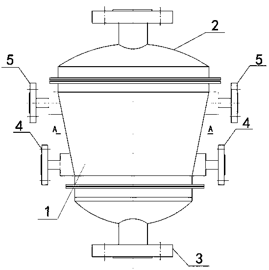
[0028] By the attachment figure 1 , 2 Shown: the heat exchanger includes a core 1, an upper header connecting flange arranged at the upper end of the core 1 and connecting the hot fluid inlet pipe 2, a lower header connecting method arranged at the lower end of the core 1 and connecting the hot fluid outlet pipe The flange 3 is arranged on the left and right sides of the core 1 at least one header connecting flange 4, 5 connecting the inlet and outlet pipes of the cooling medium, and the air inlet area of ​​the upper header connecting flange 2 is larger than that of the lower header connecting method Lan 3 outlet area.

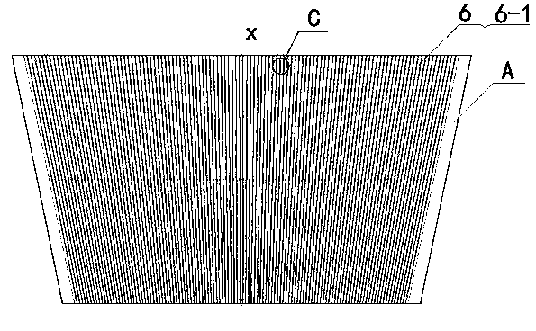
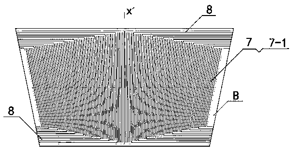
[0029] By the attachment figure 2 , 3 , 4, and 5: The core 1 is composed of a plurality of heat transfer plates A and heat transfer plates B which are alternately stacked in sequence with the top plate by diffusion welding. The heat transfer plate A adopts chemical etching and other processes on its side The surface is processed with a first variable cross-sect...


PUM


Abstract

The invention relates to a special-shaped capillary runner heat exchanger. The heat exchanger comprises a core body 1, an upper header connecting pipe flange arranged at the upper end of the core body and connected with a hot fluid inlet, a lower header connecting pipe flange arranged at the lower end of the core body and connected with a hot fluid outlet, and header connecting pipe flanges arranged on the left and right two sides of the core body and connected with cooling medium inlet and outlet pipelines by at least one; and the intake port area of the upper header connecting pipe flange is larger than the exhaust port area of the lower header connecting pipe flange. The special-shaped capillary runner heat exchanger is suitable for the working conditions of smaller size and weight of the heat exchanger according to the scene conditions: such as multiple working condition technical requirements of such system devices as ships, ocean platforms and fuel cell vehicle hydrogen refueling stations.

Description

Technical field [0001] The invention belongs to the field of heat exchange equipment, and in particular relates to a special-shaped capillary channel heat exchanger, which is used for gas liquefaction, heating, and cooling; liquid gasification, heating, cooling, and fractionation; chemical reactions and other process systems . Background technique [0002] At present, the above-mentioned fields, especially in the equipment system of large-scale high temperature, high pressure and large temperature difference heat exchange conditions, use shell and tube heat exchangers. After long-term development, the shell and tube heat exchanger technology has become mature, but due to its process and structure limitations Factors such as those may lead to problems, specifically: [0003] ①. In some major projects, the inner diameter (equivalent diameter) of the heat transfer tube of the shell-and-tube heat exchanger is larger, such as φ19mm, the tube wall is thicker, the thermal resistance incr...

Claims


Application Information

Patent Timeline
Patent Type & Authority Patents(China)
IPC IPC(8): F28D7/00F28F1/00
Inventor 马至善詹福才徐红伟荣丁石田家涛
Owner JILIN TONGDA HEAT TRANSFER TECH
Features
  • R&D
  • Intellectual Property
  • Life Sciences
  • Materials
  • Tech Scout
  • Unparalleled Data Quality
  • Higher Quality Content
  • 60% Fewer Hallucinations
Learn More