Bistatic MIMO radar high-speed target across-range-gate speed measuring and positioning method

A high-speed target and positioning method technology, applied in radio wave measurement systems, instruments, etc., can solve the problems of large transmission signal bandwidth, high spatial synthesis gain of antenna array elements, and no high-speed moving targets involved, so as to achieve precise positioning, improve The effect of estimation accuracy

Active Publication Date: 2017-02-22
XIDIAN UNIV +1
View PDF4 Cites 22 Cited by
  • Summary
  • Abstract
  • Description
  • Claims
  • Application Information

AI Technical Summary

Problems solved by technology

At present, a number of robust, real-time and efficient multi-target positioning methods have emerged. However, the existing algorithms are all aimed at stationary targets or low-speed targets, and do not involve high-speed moving targets, such as high-speed flying missiles in the air defense field, in Orbital targets in the aerospace field, etc.
Since the high-speed moving target will move across multiple range units during the echo accumulation time, that is, the high-speed moving target has crossed multiple range units during the angle estimation process. However, the existing angle estimation algorithms for bistatic MIMO radars cannot Echo accumulation is carried out across distance units, so it is difficult to effectively estimate the parameters such as DOD and DOA of high-speed moving targets in space
[0004] In response to this problem, Chen Jinli et al. proposed a method for estimating parameters such as distance and angle of high-speed moving targets in single-base MIMO radar. This method performs coherent combination of multiple output channel echo data in a short time to replace the echo data. Long-term coherent accumulation detection to reduce the impact of distance migration on tar

Method used


Image

  • Bistatic MIMO radar high-speed target across-range-gate speed measuring and positioning method
  • Bistatic MIMO radar high-speed target across-range-gate speed measuring and positioning method
  • Bistatic MIMO radar high-speed target across-range-gate speed measuring and positioning method

Examples


Embodiment Construction

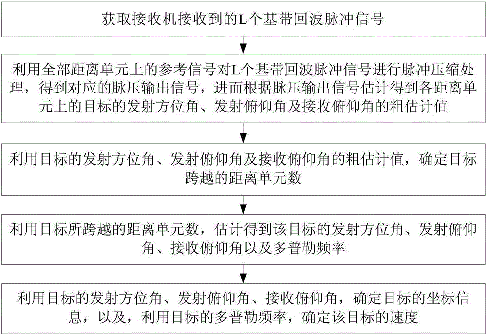
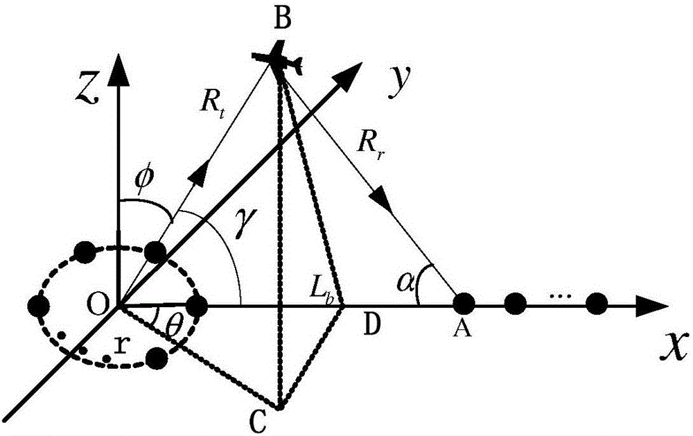
[0022] The following will clearly and completely describe the technical solutions in the embodiments of the present invention with reference to the accompanying drawings in the embodiments of the present invention. Obviously, the described embodiments are only some, not all, embodiments of the present invention. Based on the embodiments of the present invention, all other embodiments obtained by persons of ordinary skill in the art without making creative efforts belong to the protection scope of the present invention.

[0023] It should be noted that the high-speed target mentioned in the embodiment of the present invention does not specifically refer to a target whose speed is a certain value, but generally refers to a target that may walk a distance. Those skilled in the art can understand that the reason why the method provided by the implementation of the present invention limits the target to a high-speed target is that compared with a low-speed target, a high-speed targe...


PUM


Abstract

The invention belongs to the technical field of radar signal processing, and discloses a bistatic MIMO radar high-speed target across-range-gate speed measuring and positioning method. The method comprises the following steps: acquiring L baseband echo pulse signals; compressing the pulse of the L baseband echo pulse signals to get pulse output signals, and estimating the rough estimated values of the launch azimuth angle, launch pitch angle and reception pitch angle of a target; determining the number of range gates spanned by the target based on the rough estimated values of the angles of the target; estimating the angle information and Doppler frequency of the target based on the number of range gates spanned by the target; and determining the coordinate information of the target based on the angle information of the target, and determining the speed of the target based on the Doppler frequency of the target. Under the condition that a radar target has range migration, the angle information and Doppler frequency of the radar target can be estimated accurately, and the radar target can be positioned accurately.

Description

technical field [0001] The invention relates to the technical field of radar signal processing, in particular to a speed measurement and positioning method for a bistatic MIMO radar high-speed target across a range gate. Background technique [0002] The speed of modern aircraft is getting faster and faster. At present, countries all over the world are developing supersonic aircraft, represented by the X-43A test aircraft developed by the United States. Its speed reaches Mach 9.7, which poses a challenge to the traditional system of radar target detection. [0003] In recent years, in order to improve the detection performance and estimation accuracy of radar, people have widely applied Multiple-Input Multiple-Output (MIMO) technology to radar, and obtained MIMO radar. Each array element of the MIMO radar transmits orthogonal signals, and the receiving array separates the signals of each transmitting channel through a matched filter method, so a virtual 3-array can be formed...

Claims


Application Information

Patent Timeline
IPC IPC(8): G01S7/41
CPCG01S7/41
Inventor 冉艳伟金胜梁小虎徐安林李军廖桂生郭一帆祁亚楠熊媛媛袁赛
Owner XIDIAN UNIV
Why Eureka
Try Eureka