
Method and device for precisely measuring arrival time of jump edge

A technology of precise measurement and jumping edge, which is applied in the direction of measuring device, radio wave measurement system, electromagnetic wave reradiation, etc., can solve the problems of increasing chip area, unsuitability, and increasing delay unit, etc., and achieves high integration and occupied area small effect

Active Publication Date: 2017-02-22
HUAZHONG NORMAL UNIV
View PDF6 Cites 5 Cited by
  • Summary
  • Abstract
  • Description
  • Claims
  • Application Information

AI Technical Summary

Problems solved by technology

[0004] 1. The accuracy of this measurement method depends on the delay time of the delay unit. The shorter the delay time of the delay unit, the higher the accuracy, but it is still unable to measure the time interval of PS (picosecond) level
[0005] 2. The time interval that can be measured by this measurement method depends on the total delay time of the entire delay line. At the same time, in order to pursue the maximum measurement time interval, the number of delay units must be increased, thereby increasing the area of ​​the chip, which cannot be applied to lasers In a detector device with a large time interval between the emission of photoelectrons and the acceptance of photoelectrons

Method used


Image

  • Method and device for precisely measuring arrival time of jump edge
  • Method and device for precisely measuring arrival time of jump edge
  • Method and device for precisely measuring arrival time of jump edge

Examples


Embodiment 1

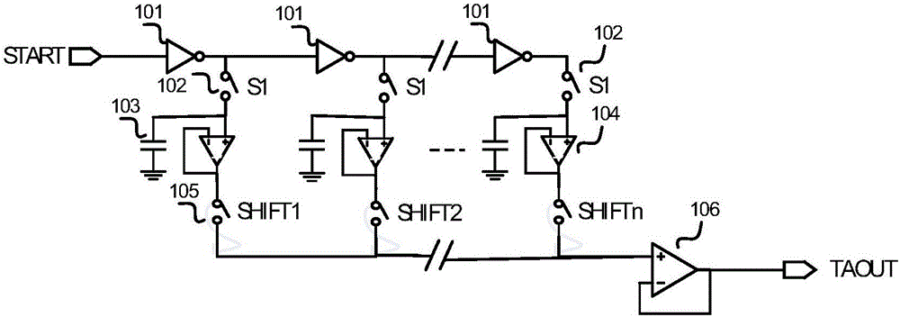
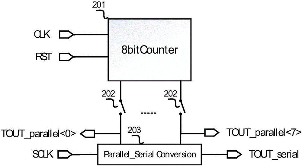
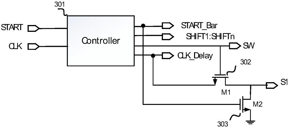
[0039] This embodiment provides a device for accurately measuring the arrival time of the jump edge, such as Figure 8As shown, it includes a fine counting module, a rough counting module, a control module and a calculation module. The arrival time signal START of the transition edge to be measured is input to the control module and the fine counting module, the reference clock signal CLK is input to the control module and the coarse counting module, the reset signal RST and the clock signal SCLK are input to the coarse counting module, The control module outputs control signals SHIFT1 to SHIFTn to the fine counting module, the control module outputs control signal S1 to the fine counting module and the coarse counting module, and the fine counting module outputs a TAOUT signal to the calculation module, The coarse counting module outputs a TDOUT_serial signal to the computing module.

[0040] figure 1 It is the structural diagram of the fine counting module of the present e...

Embodiment 2

[0054] This embodiment uses the device described in Embodiment 1 to accurately measure the method for the arrival time of the jump edge, including the following steps:

[0055] (1): Calibration: use an external high-precision TDC chip to calibrate the device of this embodiment, set the same zero time point for the external TDC chip and this device, input the same reference clock CLK, and input the same standard arrival time signal to the outside The TDC chip and the START signal input port of the device, the standard arrival moment signal includes a rising edge, and the time interval between the rising edge moment of the standard arrival moment signal and the zero moment point is less than a cycle of the reference clock CLK, and the The arrival time measured by the external TDC chip and the characteristic voltage value collected by this device are preset into the calibration table. Adjust the rising edge time of the standard arrival time signal, and then preset the arrival tim...


PUM


Abstract

The invention relates to a method and a device for precisely measuring arrival time of a jump edge. The method comprises the following steps of (1) calibration: providing multiple different standard arrival time signals, carrying out multi-stage time delay of one standard arrival time signal, subjecting signals to voltage collection and arrangement at standard specific times after each stage of time delay to obtain a feature voltage value group, obtaining feature voltage value groups of other standard arrival time signals, and forming a calibration table by multiple feature voltage value groups, multiple standard arrival times and time differences among front edges in a CLK period; (2) jump edge arrival time measurement: obtaining a to-be-detected feature voltage value group, finding a time difference between a to-be-detected arrival time and a front edge in a CLK period using the calibration table, and adding the time difference and the time of the front edge of the to-be-detected arrival time in the CLK period to obtain a to-be-detected jump edge arrival time. The measurement precision of the method is high, the measurement time interval is large, and the device structure is simple.

Description

technical field [0001] The invention relates to the field of time measurement, in particular to a method and device for accurately measuring the arrival time of a transition edge. Background technique [0002] Laser ranging is one of the applications of laser. After years of development, this technology has been successfully used in many important fields such as military affairs and aerospace. The basic principle is: the laser emits photoelectrons, the photoelectrons fly in the air, encounter obstacles and reflect back to the laser, and measure the flight time of photoelectrons in the air through the time interval measuring device inside the detector, so as to measure the distance between the laser and obstacles. In this method, the time interval measuring device plays a crucial role. [0003] At present, people generally measure the time accurately by passing the signal to be tested (single pulse signal) through a delay line. The rising edge of the signal to be tested repr...

Claims


Application Information

Patent Timeline
Patent Type & Authority Applications(China)
IPC IPC(8): G01S17/08
CPCG01S17/08
Inventor 孙向明许怒李雅淑
Owner HUAZHONG NORMAL UNIV
Learn More