Laser light source device
A laser light source and light source technology, applied in the field of projection display, can solve the problems of reducing brightness, increasing the difficulty and consumption of the second color wheel, and achieving the effect of easy implementation, reducing further consumption and improving picture quality
- Summary
- Abstract
- Description
- Claims
- Application Information
AI Technical Summary
Problems solved by technology
Method used
Image
Examples
Embodiment 1
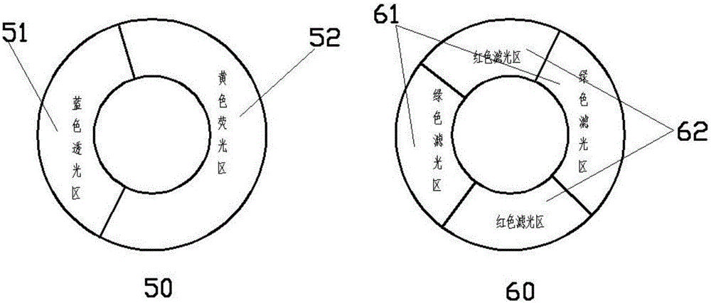
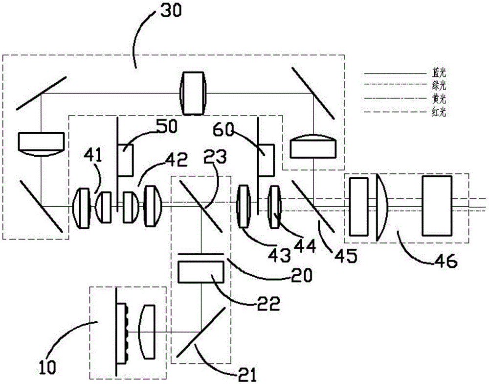
[0028] The laser light source device of the present embodiment of the present invention includes a light source exciter 10 for emitting a laser light source of at least one color; an optical path integration unit 20 and a first color wheel 50 arranged in front of the light path of the light source exciter for integrating the laser light source , the second color wheel 60, the first optical path guiding unit 30 for guiding the light source, the first collimating lens group 41, the second collimating lens group 42, the first relay lens group 43, the second relay lens group 44 , the second reflector 23, the third reflector 45, and the light source receiving unit 46 for combining the light rays transmitted and reflected by the first color wheel and the second color wheel and other components, the first color wheel 50 is opposite to the second The color wheels 60 are placed in parallel.
[0029] Such as figure 2 As shown, the light source exciter 10 in this embodiment generates b...
Embodiment 2
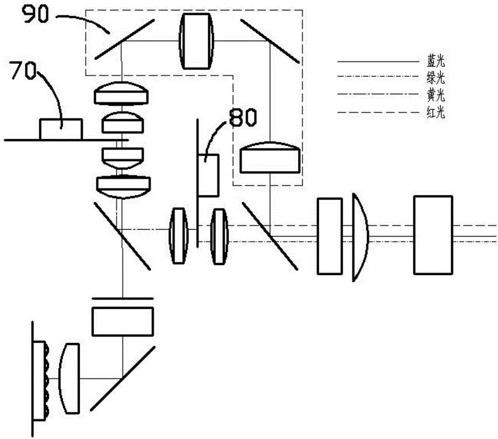
[0041] image 3 It is a schematic structural diagram of Embodiment 2 of the present invention. The difference between this embodiment and Embodiment 1 is that the first color wheel 70 of this embodiment is perpendicular to the second color wheel 80, and at the same time guides the second optical path The relay lens and reflector of 90 have been increased or decreased.
Embodiment 3
[0043] The difference between this embodiment and the first embodiment is that, if Figure 4 As shown, the first color wheel 71 of this embodiment is a transmission type, that is, in this embodiment, the yellow fluorescent area 52 is a transmission area that can transmit light. When the blue laser light passes through the yellow fluorescent area 52 of the first color wheel 71, the excited yellow light directly passes through the yellow fluorescent area 52 of the first color wheel 71, reaches the second reflector 24, and reaches the second color through transmission. wheel; when the blue laser light passes through the blue light-transmitting area 51 of the first color wheel 71 and reaches the second reflector 24 , it is reflected and reaches the third optical path guiding unit 31 .
[0044] Wherein, the second reflecting mirror 24 may be a dichroic film, which allows the reflection of blue laser light and the transmission of yellow light through coating.
PUM
 Abstract
Description
Claims
Application Information
 - R&D
- Intellectual Property
- Life Sciences
- Materials
- Tech Scout
- Unparalleled Data Quality
- Higher Quality Content
- 60% Fewer Hallucinations
Browse by: Latest US Patents, China's latest patents, Technical Efficacy Thesaurus, Application Domain, Technology Topic, Popular Technical Reports.
© 2025 PatSnap. All rights reserved.Legal|Privacy policy|Modern Slavery Act Transparency Statement|Sitemap|About US| Contact US: help@patsnap.com


