
Method, device and system for adjusting light spots received by light valve

A light valve and light spot technology, applied in the field of laser projection, can solve the problems of lack of light valve and light spot, not intuitive enough, low spot adjustment precision, etc., to achieve intuitive visibility, improve the utilization rate of light energy, and improve the degree of fit Effect

Active Publication Date: 2017-02-22
QINGDAO HISENSE LASER DISPLAY CO LTD
View PDF4 Cites 9 Cited by
  • Summary
  • Abstract
  • Description
  • Claims
  • Application Information

AI Technical Summary

Problems solved by technology

[0005] In order to solve the lack of measurement of the matching relationship between the light valve and the light spot in the prior art, which leads to low adjustment accuracy of the light spot received by the light valve and is not intuitive enough, the present invention provides a method and device for adjusting the light spot received by the light valve, system

Method used


Image

  • Method, device and system for adjusting light spots received by light valve
  • Method, device and system for adjusting light spots received by light valve
  • Method, device and system for adjusting light spots received by light valve

Examples


Embodiment Construction

[0050] In order to make the object, technical solution and advantages of the present invention clearer, the implementation manner of the present invention will be further described in detail below in conjunction with the accompanying drawings.

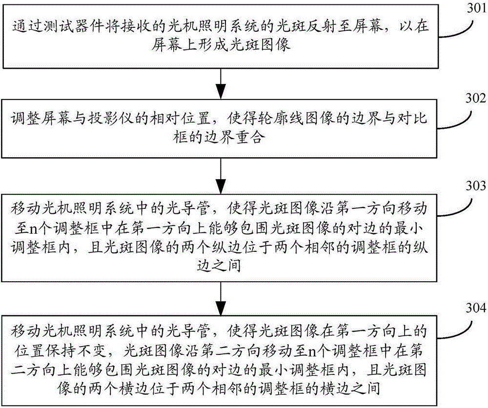
[0051] An embodiment of the present invention provides a method for adjusting a light spot received by a light valve, such as figure 2 as shown, figure 2 It is a flowchart of a method for adjusting a light spot received by a light valve provided by an embodiment of the present invention. The method is used to adjust the position of the light spot. The method may include the following steps:

[0052] Step 201 , reflecting the received light spots of the optomechanical lighting system to the screen through the test device, so as to form a light spot image on the screen. The spot image includes part or all of the contour line image.

[0053] Step 202, adjust the relative position of the boundary of the spot image and the boundary of t...


PUM


Abstract

The invention discloses a method, a device and a system for adjusting light spots received by a light valve and belongs to the field of laser projection. The method includes using a testing device for reflecting the light spots received from a light machine illuminating system to the screen and form a light spot image on the screen, wherein the light spot image comprises part or all of contour line images; adjusting the relative positions of the boundaries of the light spot image and the contour line images until an absolute value of a distance difference of at least one group of calibration distances is not more than a corresponding distance difference threshold value, wherein each group of calibration distances includes the distances between two opposite sides of the light spot image and corresponding sides of the contour line images, the size of the testing device is as same as that of the DMD light valve, the reflection surface of the testing device for light reflection is provided with contour lines, and the contour lines and boundary lines of a display region of the DMD light valve are arranged correspondingly. The method, the device and the system for adjusting the light spots received by the light valve are used for digital light processing projectors and solves the problem of low light spot adjusting precision, so that image display effects are optimized.

Description

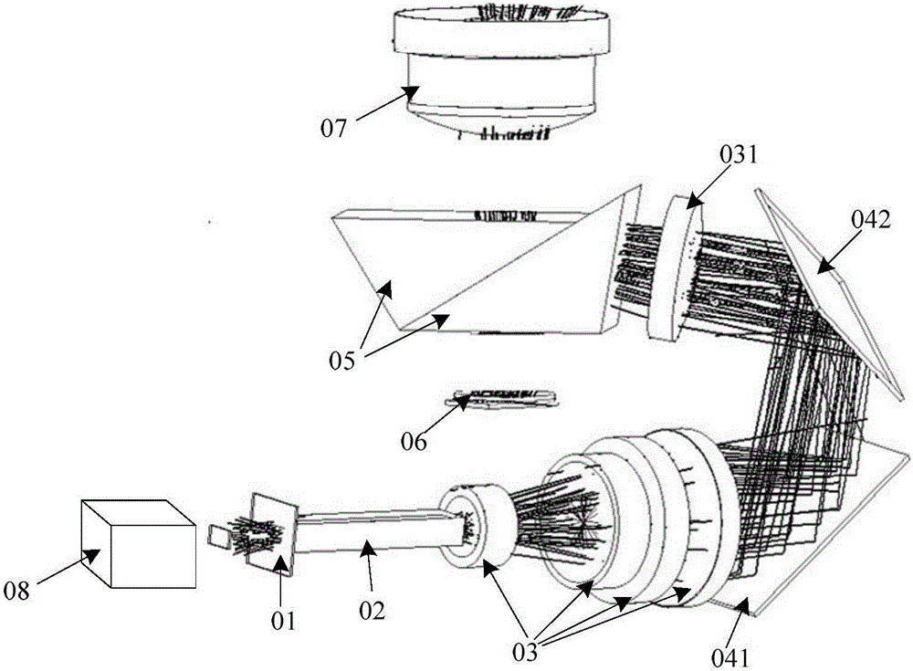
technical field [0001] The invention relates to the field of laser projection, in particular to a method, device and system for adjusting a light spot received by a light valve. Background technique [0002] A digital optical processing (English: Digital Light Processing; abbreviation: DLP) projector is integrated with a DLP projector. The DLP projector is a high-precision projector that may include: a light source, an optical-mechanical lighting system, a lens, and a screen. [0003] Such as figure 1 As shown, in practical applications, the optical path of the optomechanical lighting system can be composed of a color filter wheel 01, a light guide 02, a lens group 03, a first reflector 041, a second reflector 042, a first lens 031, total internal reflection ( English: Ttotal Internal Reflection; abbreviation: TIR) lens 05, digital micromirror device (English: Digital Micromirror Device; abbreviation: DMD) 06, wherein, DMD is the core component of the DLP projector, is a ki...

Claims


Application Information

Patent Timeline
Patent Type & Authority Applications(China)
IPC IPC(8): G03B21/28G03B21/14H04N9/31
CPCG03B21/142G03B21/28H04N9/3161
Inventor 崔荣荣郭大勃赵一石
Owner QINGDAO HISENSE LASER DISPLAY CO LTD
Learn More