
Method for rapid finite element modeling, solution and analysis based on image recognition

An image recognition and analysis method technology, applied in character and pattern recognition, special data processing applications, instruments, etc., can solve problems such as difficult to control mesh division, poor quality of finite element model, and ignoring the influence of wiring shape and distribution. , to achieve the effect of convenient programming and processing, reducing modeling difficulty and shortening modeling cycle

Inactive Publication Date: 2017-02-22
GUILIN UNIV OF ELECTRONIC TECH
View PDF4 Cites 22 Cited by
  • Summary
  • Abstract
  • Description
  • Claims
  • Application Information

AI Technical Summary

Problems solved by technology

[0005] The advantage of the first method is that it is easy to realize the precise control and adjustment of the geometric model and mesh division, so that it is easy to obtain high-quality finite element meshes, but the disadvantage is that the artificial modeling method based on coordinate information is inefficient, and when building complex models It takes a lot of time and effort, and often even complex model modeling cannot be achieved;
[0006] The advantage of the second method is that it can quickly establish a relatively complex finite element model. The disadvantage is that the mesh division is difficult to control, and the element shapes are mostly two-dimensional triangles and three-dimensional tetrahedral elements. The quality of the finite element model is often poor. In addition, when the modeling object is too complex, the model has to be simplified, resulting in the loss of many details. The calculation results are easily affected by the mesh division, element shape, and loss of details, and the analysis accuracy is poor.
[0007] At present, the two existing modeling methods of finite element CAE software have huge limitations in actual modeling, and cannot meet the modeling needs of complex research objects in many fields such as structure, shape, material composition and phase composition.
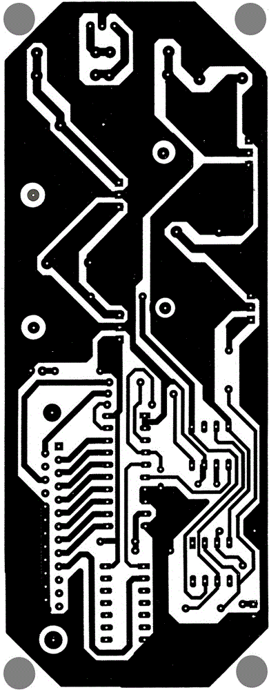
For example, in the electronics industry, the wiring system of the PCB in the printed circuit board is very complex, and each component material and structure form is extremely irregular and has multiple layers. CAE software has two modeling methods that cannot achieve modeling
Therefore, in the existing research on reliability at home and abroad, the influence of wiring shape and distribution is usually not considered, and the wiring layer is considered to be a uniform material.
However, a large number of product failure cases and scientific research have found that the differential distribution of wiring in printed circuit boards has a direct impact on the reliability of electronic products and equipment
In material engineering, the phase shape in the tissue is extremely complex and the distribution is extremely uneven, and it cannot be modeled in CAE software. Existing research usually considers the material to be homogeneous, and it is considered a homogeneous substance when modeling, which is not true. However, existing studies have shown that the elastic modulus, Poisson's ratio, hardness, electrical conductivity, and thermal conductivity of different phases in the material structure often have huge differences, and the mechanical, electrical and thermal properties of different phases The difference in thermal behavior has a significant impact on the physical properties and reliability of materials, especially for mesoscopic and microscopic materials.
Some researchers have reconstructed the microcosmic and mesoscopic finite element models of multi-phase materials with complex structures by using sequential images. However, these techniques use sequential images to establish the contour geometric model of each phase material in the CAD software platform through image processing, and then through The finite element CAE software divides the mesh, which essentially adopts the second modeling method in the finite element CAE software, so the element shape is an irregular triangle or tetrahedron, the mesh quality is poor, and there is a finite element analysis accuracy not high disadvantage

Method used


Image

  • Method for rapid finite element modeling, solution and analysis based on image recognition
  • Method for rapid finite element modeling, solution and analysis based on image recognition
  • Method for rapid finite element modeling, solution and analysis based on image recognition

Examples


Embodiment

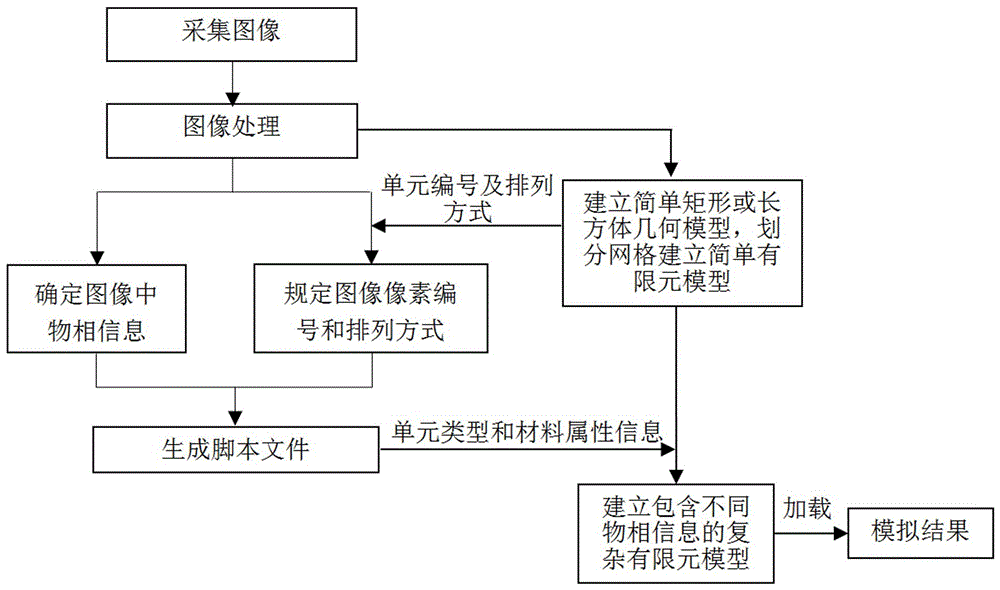
[0035] A rapid finite element modeling and solution analysis method based on image recognition, comprising the following steps:

[0036] 1) Collect images through digital equipment or engineering drawings, enhance the images and adjust the pixel size according to actual needs;

[0037] 2) Establish a two-dimensional rectangular or three-dimensional cuboid geometric model in the CAE software and realize the mesh division of the geometric model to obtain a simple finite element model;

[0038] 3) According to the unit number and arrangement method of the simple finite element model, the image pixel number and arrangement method are stipulated;

[0039] 4) Determine the phase information of all numbered pixels in the image according to the color value information of the pixels in the image;

[0040] 5) The generated finite element CAE software can recognize the script file, which contains the number of each pixel and its corresponding phase information;

[0041] 6) Read the scr...


PUM


Abstract

The invention discloses a method for rapid finite element modeling, solution and analysis based on image recognition. The method comprises the steps that an image is collected; a two-dimensional rectangular or three-dimensional cuboid geometric model is established, and grid division of the geometric model is carried out; according to unit numbers and an arrangement mode of a simple finite element model, and pixel numbers and the arrangement mode are stipulated; phase information of all the numbered pixels in the image is determined; a script document which can be recognized by finite element CAE software is generated; the script document is read, material attributes and unit type information of units with the same numbers in the simple finite element model are assigned or modified according to the phase information of each pixel of the script document, and a complicated finite element model containing different unit types and material attribute information is generated; and the complicated finite element model which contains the different unit types and material attribute information is loaded, solved and analyzed, so that a simulation result is obtained. The method has the advantage that the rapid and highly accurate finite element modeling can be achieved, and solution and analysis can be carried out; and deficiencies in a current finite element CAE software modeling method can be solved.

Description

technical field [0001] The invention belongs to the field of computer-aided engineering, and in particular relates to a fast finite element modeling and solution analysis method based on image recognition, thereby realizing direct finite element modeling and loading and solving in CAE software; it can be used as an existing CAE software or platform limited Supplementary to the meta-modeling method, applied to mechanical parts composed of different or complex structures and materials, electronic devices, and material systems and physical systems composed of different phases in mainstream finite element CAE software and platforms (such as ANSYS, MARC, ABAQUS , MSC / PATRAN, COMSOL, etc.) for 2D and 3D finite element modeling, and realize loading solutions. Background technique [0002] Since the beginning of the 21st century, computer-aided engineering (Computer Aided Engineering, CAE for short) software based on the finite element method, such as ANSYS, MARC, ABAQUS, PATRAN, C...

Claims


Application Information

Patent Timeline
IPC IPC(8): G06F17/50G06K9/46
CPCG06F30/23G06V10/56
Inventor 秦红波王瑛王珊珊冯闯栾兴贺杨道国
Owner GUILIN UNIV OF ELECTRONIC TECH
Learn More