Self-healing parallel capacitor structure

A capacitor structure, self-healing technology, applied in the field of electric power, can solve the problems of fire, capacitor heat is difficult to dissipate, and life is not long, etc., to achieve the effect of simple thin-walled structure, good product heat dissipation, and high production efficiency

Active Publication Date: 2017-02-22
KBR POWER QUALITY MANAGEMENT SHANGHAI
View PDF4 Cites 2 Cited by
  • Summary
  • Abstract
  • Description
  • Claims
  • Application Information

AI Technical Summary

Problems solved by technology

Especially for dry self-healing shunt capacitors filled with hard resin, this protection is not only closely related to the top cover of the capacitor, but also closely related to the pressure relief channel of the capacitor. Currently, due to structural limitations in the use of such capacitors , the design of the pressure relief channel is unreasonable, so that the capacitor cannot be quickly removed from the power grid when it fails, and the belly explosion phenomenon occurs from time to time, and even catches fire. There are potential safety hazards and unnecessary losses to customers.
[0003] Most of the self-healing shunt capacitors are connected by copper wires. When the copper wires are connected to the components, the multi-strands are scattered, which brings great difficulties to the welding. False soldering occurs from time to time, and the copper wire routing path is placed in the core tube. The center of the entire capacitor, the disadvantage of this connection method is that the contact resistance of the capacitor is very large, the heat is difficult to dissipate when the capacitor is in normal operation, and there is a great potential safety hazard
[0004] The structure design of the inner bottom cover of the capacitor is unreasonable, so that the resin cannot be fully filled into every corner of the capacitor
Affects heat shrinkage and heat dissipation of capacitors
Capacitor performance is unstable and life is not long

Method used


Image

  • Self-healing parallel capacitor structure
  • Self-healing parallel capacitor structure
  • Self-healing parallel capacitor structure

Examples


Embodiment Construction

[0024] The present invention will be further described below in conjunction with the accompanying drawings and specific embodiments.

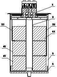
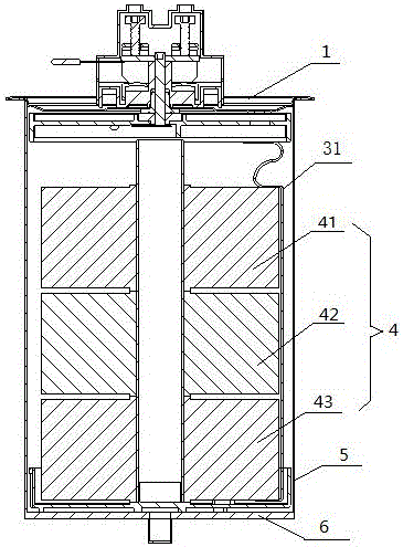
[0025] The internal structure capacitor disclosed by the present invention, such as figure 1 As shown, it includes a top cover 1, a pressure relief pipe 2, an insulating copper tape 3, an element 4, an aluminum can 5, a bottom cover 6 and resin inside the aluminum can 5. The resin is filled in the gap between the aluminum can 5 , the top cover 1 , the bottom cover 6 and the element 4 . The thickness of the hollow thin-walled ring is 0.3mm-0.5mm; the thickness of the pressure relief pipe is 0.2mm-0.5mm; the thickness of the wide sheet structure is 0.5mm-0.8mm.

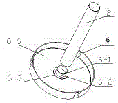
[0026] Such as figure 1 with 3 As shown, there is a hollow thin-walled ring structure 6-2 in the middle of the upper part of the bottom cover 6. The top of this structure adopts a rounded structure 6-1. There is a stepped circular structure 6 at the connection between the bottom of th...


PUM


Abstract

The invention discloses a self-healing parallel capacitor structure. The self-healing parallel capacitor structure comprises a top cover, an aluminum tank, an element, a pressure relief pipe, a bottom cover, an insulating copper belt and resin, wherein the top cover is arranged at the top of the aluminum tank; the bottom cover is arranged at the bottom of the aluminum tank; the aluminum tank is internally equipped with the insulating copper belt and the element; a hollow thin-wall circular ring is arranged in the middle of the upper part of the bottom cover; one end of the pressure relief pipe is connected with the hollow thin-wall circular ring and the other end of the pressure relief pipe is connected with the top cover; a connection part of the pressure relief pipe and the bottom cover is in interference fit and has no gap, and a pressure relief channel is formed; a ladder-shaped round structure is arranged at a connection part of the hollow thin-wall circular ring and the bottom cover; the element is supported by the ladder-shaped round structure; the insulating copper belt is connected with the top cover through welding; the insulating copper belt is distributed at the outer side of the element; gaps among the aluminum tank, the top cover, the bottom cover and the element are filled with resin. According to the self-healing parallel capacitor structure disclosed by the invention, problems that pressure relief and welding are difficult are solved; the self-healing parallel capacitor structure is simple in structure and convenient in assembling; the product has a good heat dissipation property and stable performances, is safe to operate and is long in service life.

Description

technical field [0001] The invention belongs to the field of electric power and relates to a capacitor, in particular to a self-healing parallel capacitor structure. Background technique [0002] Capacitors are widely used as a reactive power source for reactive power compensation in domestic power systems, and their reliable operation is directly related to the safe, stable and economical operation of the power system. When the capacitor reaches the end of its service life or when there is overvoltage or overcurrent for a long time, a very high pressure will be generated inside. When the internal pressure of the capacitor reaches the threshold value of the action, the top of the capacitor will bulge, and the terminal will be disconnected from the internal connection, thereby disconnecting from the capacitor. The power grid is disconnected to achieve the protection effect. Especially for dry self-healing shunt capacitors filled with hard resin, this protection is not only c...

Claims


Application Information

Patent Timeline
Patent Type & Authority Applications(China)
IPC IPC(8): H01G2/10H01G4/224
CPCH01G2/10H01G4/224
Inventor 李苗苗
Owner KBR POWER QUALITY MANAGEMENT SHANGHAI
Why Eureka
Try Eureka