
Pyramid horn filtering antenna based on waveguide structure

A filter antenna and waveguide structure technology, which is applied in the direction of waveguide horn, antenna, antenna grounding switch structure connection, etc., can solve the problem that waveguide horn antenna is difficult to have filtering characteristics, low sidelobe level, and small sidelobe level at the same time. Achieve the effect of simple and reliable structure, low cross polarization and reduced side lobe

Pending Publication Date: 2017-02-22
SOUTH CHINA UNIV OF TECH
View PDF4 Cites 2 Cited by
  • Summary
  • Abstract
  • Description
  • Claims
  • Application Information

AI Technical Summary

Problems solved by technology

[0006] The purpose of the present invention is to solve the defect that waveguide horn antennas in the prior art are difficult to possess filtering characteristics and low sidelobe levels at the same time, and provide a pyramidal horn filter antenna based on waveguide structure, which has simple structure, easy tuning, Advantages of high frequency selectivity, small side lobe level and flat gain

Method used


Image

  • Pyramid horn filtering antenna based on waveguide structure
  • Pyramid horn filtering antenna based on waveguide structure
  • Pyramid horn filtering antenna based on waveguide structure

Examples


Embodiment

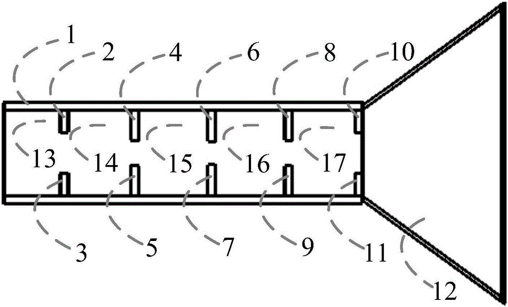
[0031] The cross-sectional view of the waveguide filter antenna structure of the present invention is as follows image 3 As shown, the structure is symmetrical. The waveguide-based pyramid horn filter antenna includes: a metal waveguide cavity 1 and a pyramid horn 12 .

[0032] The pyramid horn 12 opens along the E plane and the H plane at the same time, and is mainly used to improve the radiation gain and directivity of the antenna and reduce the sidelobe level.

[0033] The metal waveguide cavity 1 is rectangular.

[0034] One end of the metal waveguide cavity 1 is used as a signal input port 13 , and the other end is connected to the pyramid horn 12 as a radiation port.

[0035] The metal waveguide cavity 1 is sequentially composed of the first inductance diaphragm 2 and the second inductance diaphragm 3, the third inductance diaphragm 4 and the fifth inductance diaphragm 5, the fifth inductance diaphragm 6 and the sixth inductance diaphragm 7, The seventh inductive dia...


PUM


Abstract

The invention discloses a pyramid horn filtering antenna based on a waveguide structure. The filtering antenna has a filtering characteristic and a radiation characteristic at the same time, wherein the filtering characteristic is generated by four rectangular resonant cavities, and the radiation characteristic is generated by the last stage of resonant cavity and a pyramid horn together. The coupling strength between the adjacent resonant cavities, the external quality factor of a filter and the radiation quality factor of the antenna can be controlled by adjusting the width of an inductance diaphragm window. When the external quality factor of the filter is equal to the radiation quality factor of the antenna, mutual influence of a filtering unit and a radiation unit can be avoided. By introducing the pyramid horn, the radiation gain and directionality of the antenna can be improved, and the minor lobe is reduced. The filtering antenna provided by the invention has the advantages of gain flatness, high selectivity, low minor lobe, low cross polarization, simple and reliable structure and easiness integration, and is applicable to various communication systems.

Description

technical field [0001] The invention relates to the technical field of wireless communication, in particular to a pyramidal horn filter antenna based on a waveguide structure. Background technique [0002] Antennas and microwave filters are essential key components for modern microwave relay communication, satellite communication, wireless communication and other systems. The main purpose of the antenna is to transmit and receive electromagnetic signals, and to control the radiation direction of the signal. The main function of microwave filters is to filter out unwanted signals, that is, pass useful signals in a certain frequency range with low loss, and attenuate frequency components in other frequency ranges to an extremely low level. Antenna and microwave filter are one of the important components in the circuit system. Their performance largely determines the working quality of the system, and their size directly affects the size and portability of the entire system. ...

Claims


Application Information

Patent Timeline
Patent Type & Authority Applications(China)
IPC IPC(8): H01Q1/50H01Q13/02H01Q13/08
CPCH01Q1/50H01Q13/02H01Q13/08
Inventor 陈付昌陈健锋
Owner SOUTH CHINA UNIV OF TECH
Learn More