Intelligent cooling system for traction converter of electric multiple unit

A technology for traction converters and cooling systems, applied in cooling/ventilation/heating transformation, modification with gaseous coolant, electrical components, etc., can solve the problem of inability to accurately control the heat transfer process of heat sources and energy utilization in traction converters Low efficiency, constant adjustment of cooling intensity, etc., to improve heat dissipation efficiency and energy utilization efficiency, reduce auxiliary power consumption, and meet energy saving effects

Active Publication Date: 2017-02-22
CRRC DALIAN INST CO LTD
View PDF9 Cites 8 Cited by
  • Summary
  • Abstract
  • Description
  • Claims
  • Application Information

AI Technical Summary

Problems solved by technology

In the prior art, the cooling system adopted by the heat source in the equipment cabin under the electric train set has the disadvantages of constant cooling intensity adjustment and low energy utilization efficiency; some cooling systems used in electric train sets such as traction transformer cooling system, The traction converter cooling system and traction motor cooling system are still passive cooling systems. The heat dissipation design standard of these cooling systems is to meet the heat dissipation requirements at full load, and the control strategy is an extensive single-point control method. Take the cooling system as an example. The general control strategy in the prior art is: the fan used in the cooling system has two speed operatio

Method used


Image

  • Intelligent cooling system for traction converter of electric multiple unit
  • Intelligent cooling system for traction converter of electric multiple unit

Examples


Embodiment Construction

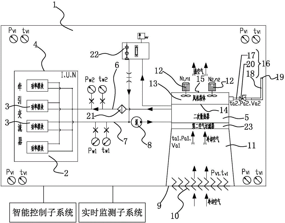
[0048] like figure 1 and figure 2 Shown is an intelligent cooling system for the traction converter of an electric multiple unit, the electric multiple unit has an equipment cabin 1, the traction converter 2 is arranged in the equipment cabin 1, and the cooling system includes: installing the traction The primary radiator 4 of the heat source component 3 included in the converter 2, and the secondary cooling device arranged in the equipment compartment 1; the cooling fluid flowing out of the primary radiator 4 takes away the heat source component 3 to generate heat; the secondary cooling device includes: a secondary radiator 5 communicated with the primary radiator 4 through a coolant circulation pipeline; the coolant circulation pipeline includes a liquid inlet pipeline 6 and a liquid outlet pipeline 7; the pump 8 installed on the liquid outlet pipeline 7; the cooling liquid flowing out from the primary radiator 4 enters the secondary radiator 5 through the liquid outlet pi...


PUM


Abstract

The invention discloses an intelligent cooling system for a traction converter of an electric multiple unit. The intelligent cooling system comprises a primary heat sink and a secondary cooling device, wherein the primary heat sink is used for installing a heat source part contained in the traction converter, the secondary cooling device is arranged in equipment compartment, heat generated by the heat source part is taken away by a cooling liquid flowing out of the primary heat sink, the secondary cooling device comprises a secondary heat sink and a pump, the secondary heat sink communicates with the primary heat sink through a cooling liquid circulation pipeline, the cooling liquid circulation pipeline comprises a liquid inlet pipeline and a liquid outlet pipeline, the pump is arranged on the liquid outlet pipeline, the cooling liquid flowing out of the primary heat sink passes through the liquid outlet pipeline and the pump and enters the secondary heat sink, the secondary heat sink is used for transferring the heat to cooling air from the cooling liquid, and the cooling liquid passes through the liquid inlet pipeline and returns to the primary heat sink after the heat is released. By the intelligent cooling system, the rotational speed of a draught fan and the flow quantity of the cooling air can be dynamically regulated according to a running environment and a working condition of the electric multiple unit so as to further control cooling intensity, and excessive cooling is prevented.

Description

technical field [0001] The invention relates to the technical field of heat exchange, in particular to an intelligent cooling system for traction converters of electric trains. Background technique [0002] At present, the intelligent cooling technology applied to electric multiple units has not been fully understood and paid enough attention to. In the prior art, the cooling system adopted by the heat source in the equipment cabin under the electric train set has the disadvantages of constant cooling intensity adjustment and low energy utilization efficiency; some cooling systems used in electric train sets such as traction transformer cooling system, The traction converter cooling system and traction motor cooling system are still passive cooling systems. The heat dissipation design standard of these cooling systems is to meet the heat dissipation requirements at full load, and the control strategy is an extensive single-point control method. Take the cooling system as an...

Claims


Application Information

Patent Timeline
IPC IPC(8): H05K7/20H02M1/00
CPCH02M1/00H05K7/20145H05K7/20172H05K7/20181H05K7/20209H05K7/20272
Inventor 孔丽君刘俊杰严兵于瀚翔
Owner CRRC DALIAN INST CO LTD
Why Eureka
Try Eureka