

An automatic feeding device for high-temperature powder materials and its application
An automatic feeding device and powder material technology, applied in the direction of feeding devices, chemical/physical processes, chemical instruments and methods, etc., can solve the problems of inaccurate gas-solid two-phase fluid measurement and automation, and avoid weighing The effect of heavy accuracy, intuitive feeding flow, and high degree of automation
- Summary
- Abstract
- Description
- Claims
- Application Information
AI Technical Summary
Problems solved by technology
Method used
Image

Examples
Embodiment 1
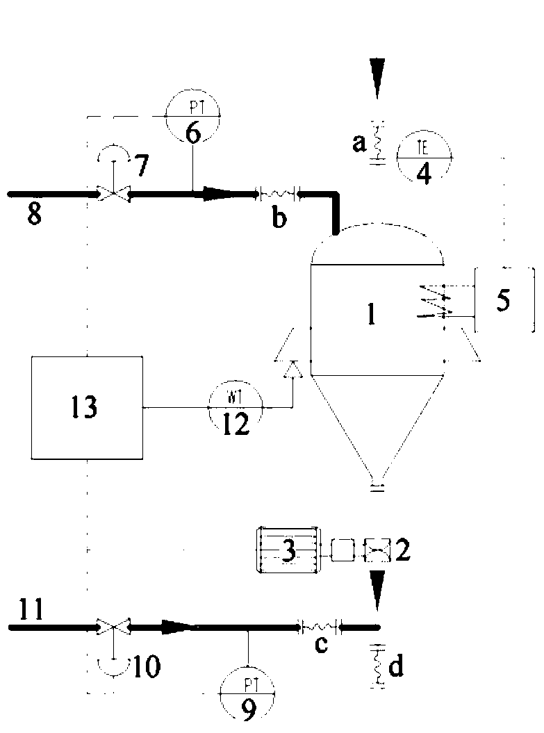
[0030] A high-temperature powder automatic feeding device (parts such as figure 1 shown), including a feed bin 1 and a feeding system connected from top to bottom; the feeding system includes a feeder 2, and the feeder 2 inlet is directly connected with the feeder 1 outlet;
[0031] The device also includes a temperature control system, a voltage stabilizing system, a weight sensor 12 and an automatic control system 13;
[0032] The temperature control system includes a heater 5 and a temperature transmitter 4 that are respectively connected to the feed bin 1; the heater 5 and the temperature transmitter 4 are also connected to an automatic control system 13 respectively;
[0033] The pressure stabilizing system includes a feed end voltage stabilizing unit connected to the inlet of the silo 1 and a discharge end voltage stabilizing unit connected to the outlet of the feeder 2; in the feed end stabilizing unit, one end of the pressure sensor 6 is connected to the The inlet of ...
Embodiment 2
[0037] A high-temperature powder automatic feeding device (such as figure 1 shown), compared with Example 1, the difference is only that nitrogen is introduced into the working air ducts 8 and 11, the feed pipe connected to the inlet of the feed bin 1 is provided with a flexible connection a, and the feed pipe connected to the feeder 2 outlet The discharge pipe is provided with a soft connection d, the working air channel 8 of the pressure stabilizing unit at the feed end is connected with the inlet of the silo 1, and the working air channel 11 of the pressure stabilizing unit at the discharge end is connected with the outlet of the feeder 2 Set up a soft connection c.
Embodiment 3
[0039] A high-temperature powder automatic feeding device (such as figure 1 shown), compared with Example 2, the difference is only that: the temperature control system monitors the temperature in the silo in real time, the pressure stabilizing system monitors the pressure at the silo inlet and the feeder outlet in real time, and the weight The sensor monitors the weight of the material in the silo in real time, and each component transmits the monitoring signal to the automatic control system in real time;
[0040] At the same time, the automatic control system sets preset values for temperature, pressure, and material flow. After receiving the temperature, pressure, and material weight monitoring signals, it processes the signals and calculates the actual value, and compares the actual value with the preset value. In comparison, if the actual value deviates from the preset value, the automatic control system transmits an adjustment signal to the outside to adjust the tempe...
PUM
 Abstract
Description
Claims
Application Information