Method for automatically measuring gain linearity of traveling wave tube

A technology of automatic measurement and traveling wave tube, applied in the direction of vacuum tube testing, etc., can solve the problems of poor measurement accuracy and low measurement efficiency, and achieve the effects of improving measurement accuracy, reducing observation and recording errors, and shortening measurement time

Inactive Publication Date: 2017-03-01
UNIV OF ELECTRONIC SCI & TECH OF CHINA
View PDF3 Cites 3 Cited by
  • Summary
  • Abstract
  • Description
  • Claims
  • Application Information

AI Technical Summary

Problems solved by technology

[0004] The object of the present invention is to provide an automatic measurement method for the gain linearity of a traveling wave

Method used


Image

  • Method for automatically measuring gain linearity of traveling wave tube
  • Method for automatically measuring gain linearity of traveling wave tube
  • Method for automatically measuring gain linearity of traveling wave tube

Examples


Embodiment Construction

[0019] The present invention will be described in further detail below in conjunction with specific embodiments and drawings; the embodiments are only used to explain the present invention, and are not intended to limit the present invention.

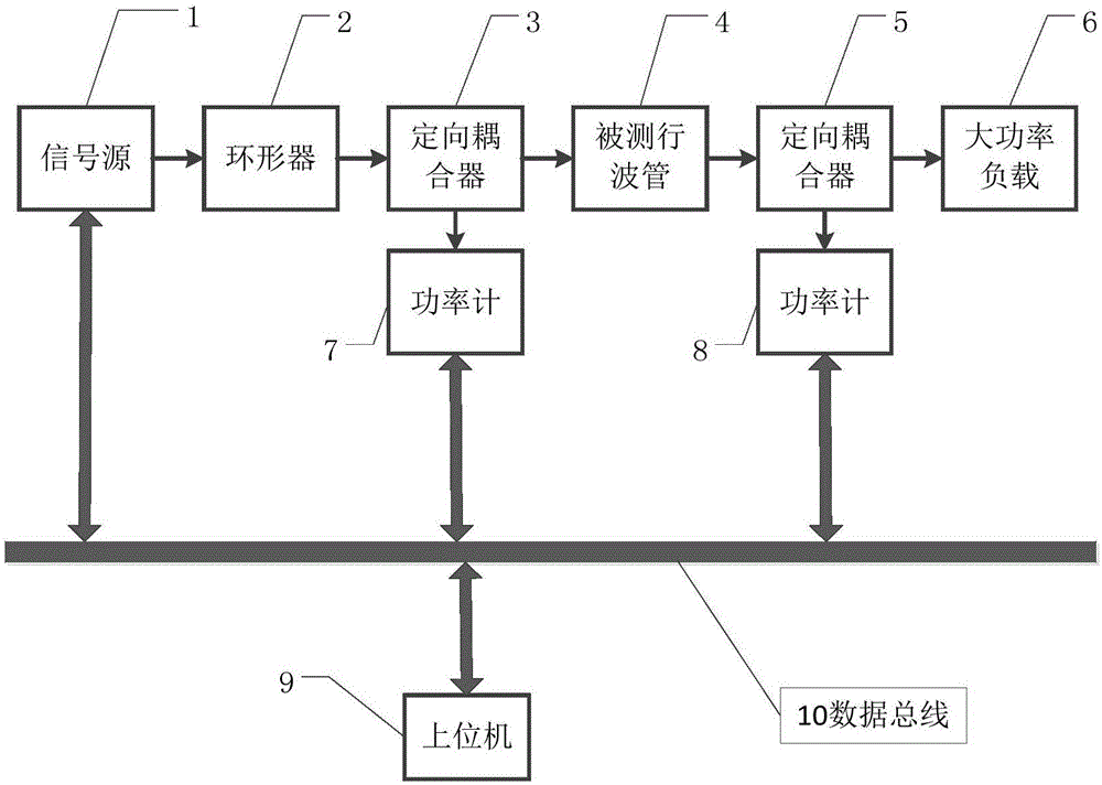
[0020] Such as figure 1 Shown is a structural block diagram of the measurement system of the present invention, including a signal source 1, a circulator 2, a directional coupler 3, a measured traveling wave tube 4, a directional coupler 5, a high-power load 6, a power meter 7, a power meter 8, Host computer 9, data bus 10; a circulator 2 is added between the signal source 1 and the directional coupler 3 to prevent the signal source from being damaged by the reflected signal caused by the mismatch of the measurement line.

[0021] The process of measuring an input and output point of the TWT to be tested at a specific frequency is as follows: the host computer 9 transmits instructions to the signal source 1 through the data bus 10, cont...


PUM


Abstract

The invention belongs to the technical field of automatic testing, and provides a method for automatically measuring the gain linearity of a traveling wave tube, so as to solve problems that a conventional measurement method is low in measurement efficiency, and is poor in measurement precision. The method employs an upper computer to control and complete the whole measurement process, and comprises the steps: firstly carrying out the power scanning of a to-be-measured traveling wave tube at a specific measurement frequency point; secondly carrying out the fitting of the input and output power data of the to-be-measured traveling wave tube through high-order polynomial curve fitting, and calculating the gain linearity according to a fitting curve; finally carrying out the frequency scanning, and completing the measurement of the gain linearity at each measurement frequency point (the whole frequency band). Only initialization measurement parameters need to be set in the whole measurement process, and there is no need to carry out manual intervention, thereby greatly shortening the measurement time, and remarkably improving the measurement efficiency. Moreover, the method effectively reduces the unavoidable observation and record errors at a manual measurement link, and greatly improves the measurement precision.

Description

technical field [0001] The invention belongs to the technical field of automatic testing, and in particular relates to a method for automatically measuring the gain linearity of a traveling wave tube. Background technique [0002] Traveling wave tube is a kind of microwave vacuum electronic device widely used in modern military and communication fields, and plays a very important role. The gain linearity of the traveling wave tube is an index parameter that characterizes the gain flatness of the traveling wave tube in the linear amplification region. Ideally, the gain of the TWT in the linear region is a constant, but currently, due to the manufacturing precision and the nonlinear characteristics of the material, the gain of the TWT has non-negligible fluctuations in the linear region. [0003] At present, the measurement of the linearity of the power gain of the traveling wave tube requires the tester to manually adjust the output of the signal source to drive the travelin...

Claims


Application Information

Patent Timeline
IPC IPC(8): G01R31/25
CPCG01R31/25
Inventor 刘宇黄桃宫大鹏周小社
Owner UNIV OF ELECTRONIC SCI & TECH OF CHINA
Why Eureka
Try Eureka