
Improved low-pressure casting wheel mold

A low-pressure casting and mold technology, applied in the field of low-pressure casting molds for aluminum wheels, can solve problems such as low mechanical properties, low performance, and low air heat transfer capacity, and achieve the effects of improving mechanical properties, increasing solidification speed, and strengthening cooling strength.

Inactive Publication Date: 2017-03-08
CITIC DICASTAL
View PDF5 Cites 2 Cited by
  • Summary
  • Abstract
  • Description
  • Claims
  • Application Information

AI Technical Summary

Problems solved by technology

However, this unique shape makes the intersection of the spoke and the rim very thick, forming a typical casting hot spot, which is obviously not conducive to the sequential solidification and forming of wheel castings.
Practice shows that casting problems such as shrinkage porosity, shrinkage cavity, and low performance are prone to occur in the junction area between the spoke and the rim, and the resulting waste wheels also account for a large proportion, which seriously restricts the yield
In the prior art, the cooling at the hot spot is generally realized by arranging a certain number of air ducts, but because the heat is too concentrated and the heat exchange capacity of the air is low, the heat in this area cannot be dissipated quickly and effectively. out, resulting in slow solidification of the molten aluminum, forming defects such as shrinkage porosity and shrinkage cavities will occur due to insufficient feeding; in addition, the supercooling degree of the molten aluminum during solidification will be correspondingly low, resulting in coarse grains inside the casting and microstructure. Not dense, low mechanical properties, these seriously affect the forming quality of the wheel, restricting the development of the enterprise

Method used


Image

  • Improved low-pressure casting wheel mold
  • Improved low-pressure casting wheel mold
  • Improved low-pressure casting wheel mold

Examples


Embodiment Construction

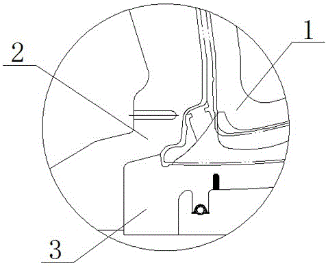
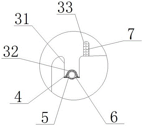
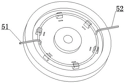
[0012] Figure 1-Figure 3 As shown, an improved low-pressure casting wheel mold includes a top mold 1, a side mold 2, and a bottom mold 3. The three together form a mold cavity, which ensures the smooth forming of the wheel casting; the root of the bottom mold 3 back cavity corresponds to A columnar boss 31 is set at the hot joint, the number of which is the same as the number of spokes, and it is used as a cooling source for the spot cold at the hot joint; a U-shaped through groove 32 is processed on the cylindrical boss 31, and a heat conducting gasket 4 is placed in the groove. You can choose red copper, graphite sheet, etc. with excellent thermal conductivity, with a thickness of 1-3mm; place the prepared annular water pipe 5 on the gasket in the groove, and the lower part of the water pipe should be higher than the end surface of the columnar boss, so as to ensure that the cover plate 6 can Tightly fix it in the groove, and achieve a good fit between the water pipe and th...


PUM

PropertyMeasurementUnit
Thicknessaaaaaaaaaa

Abstract

The invention discloses an improved low-pressure casting wheel mold. Columnar bosses (31) are arranged at the positions, corresponding to hot joints, of the root of a back cavity of a bottom mold (3), and the number of the bosses is consistent with the number of spokes; U-shaped through grooves (32) are formed in the bosses (31), heat conduction gaskets (4) are placed in the grooves, annular water pipes (5) are placed on the heat conduction gaskets (4) in the grooves, the lower portions of the annular water pipes (5) are higher than the end faces of the columnar bosses (31), heat insulation grooves (33) are formed in the front ends of the columnar bosses (31), the distance between the mold bottom and the mold cavity face ranges from 10 mm to 20 mm, and the grooves are jammed with heat insulation asbestos; the improved low-pressure casting wheel mold is simple in structure, a bottom mold structure is reasonably improved, the columnar bosses are machined according to the spoke heat joint areas to serve as cooling sources, cooling is controlled within the heat joint range, the temperature distribution of the front end is not affected, and more precise refrigeration is achieved.

Description

technical field [0001] The invention relates to the field of casting, in particular to a low-pressure casting mold for an aluminum wheel. Background technique [0002] Low-pressure casting technology is the primary choice of domestic and foreign aluminum wheel manufacturers. The bottom mold, top mold, and side molds together constitute the mold cavity. Driven by external pressure, the high-temperature aluminum liquid enters the mold cavity from the bottom center gate, and completes the solidification and forming under the joint action of the mold and external cooling. Dimensions, qualified castings. The center of the shaped flange of the wheel is thick, the wall thickness of the rim is thin, and the spokes are in the middle as the connecting part of the two. However, this unique shape makes the intersection of the spoke and the rim very thick, forming a typical casting hot spot, which is obviously not conducive to the sequential solidification and forming of wheel castings...

Claims


Application Information

Patent Timeline
IPC IPC(8): B22D18/04
CPCB22D18/04
Inventor 王凯庆李鸿标汪煦李昌海赵永旺周洪海
Owner CITIC DICASTAL
Learn More