Tool electrode high-speed rotation electromachining electric conduction device

A high-speed rotation, tool electrode technology, applied in electric processing equipment, manufacturing tools, metal processing equipment and other directions, can solve the problems of complex device structure, mercury toxicity, high cost, and achieve the effects of good economic benefits, easy implementation and simple structure

Active Publication Date: 2017-03-08
颍上县祥盛建设管理有限公司
View PDF10 Cites 13 Cited by
  • Summary
  • Abstract
  • Description
  • Claims
  • Application Information

AI Technical Summary

Problems solved by technology

The Chinese patent No. 201520514464.4 discloses a rotary power supply device for rotary kiln. The device is in contact with the slip ring line through the brush, and uses the brush method to conduct electricity. This method can use multiple collectors for power supply, making the power supply more stable. , but the disadvantage is that the brush wear is very serious under high-speed rotation; the Chinese patent No. 201520914971.7 discloses a mercury slip ring device, which uses mercury to conduct current transmission, no wear between the stator and the rotor, and high transmission accuracy. Good stability, but the disadvantage is that mercury is toxic and requires high sealing conditions, especially when the temperature rises during high-speed rotation, mercury vapor is formed, which is very harmful to the health of operators; Chinese patent No. 201520625673.6 discloses a A wireless power supply ultrasonic rotating machining electric spindle, the device responds to the transmitting electromagnetic coil through the receiving electromagnetic coil, and transmits the signal to the piezoelectric ceramic transducer to generate high-frequency vibration processing. This method realizes wireless power induction, but the disadvantage is that the device Complex structure, high cost, poor economy

Method used


Image

  • Tool electrode high-speed rotation electromachining electric conduction device
  • Tool electrode high-speed rotation electromachining electric conduction device
  • Tool electrode high-speed rotation electromachining electric conduction device

Examples


Embodiment Construction

[0023] In order to express the technical means, objectives and advantages of the present invention more clearly, the present invention will be further described in detail below in conjunction with the accompanying drawings and specific embodiments. It should be understood that the specific embodiments described here are only used to explain the present invention, not to limit the present invention.

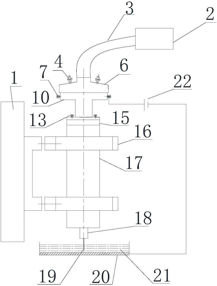
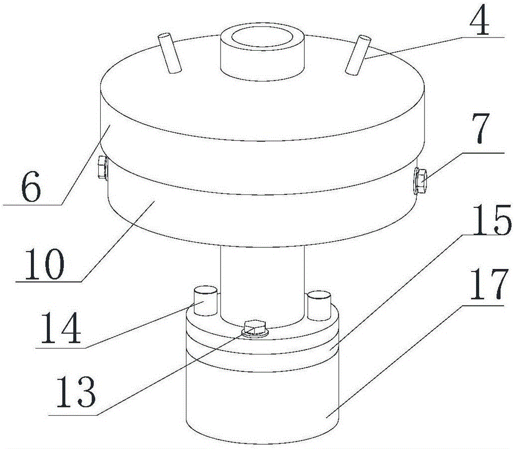
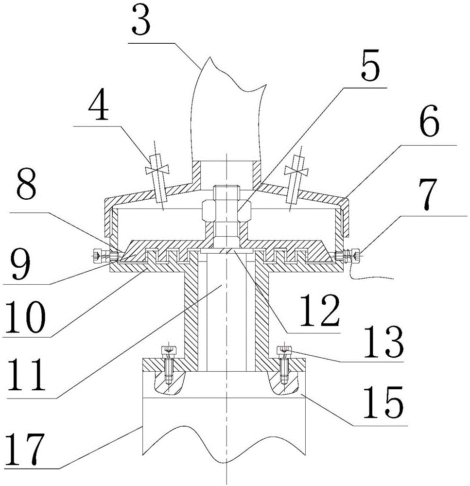
[0024] See attached figure 2 , since the main structure of the device is a rotary structure, that is, the cross-section of the device is the same, one of the cross-sections of the structure will be described below. as attached Figure 1-5 As shown, a tool electrode high-speed rotary electrical machining lead-in device includes an air pump 2, a rubber tube 3, a pressure reducing valve 4, an upper end cover 6, a lead screw 7, a conductive liquid 8, a rotating pair 9, and a fixed pair 10. One end of the rubber tube 3 is connected to the air pump 2, and the other end is sleeved on ...


PUM


Abstract

The invention discloses a tool electrode high-speed rotation electromachining electric conduction device. The device comprises an air pump, a rubber tube, an upper end cover, a reducing valve, a revolution joint, a conducting solution, a fixed joint and an electric conduction screw. By the adoption of the device, the abrasion problem of an electric brush in a traditional electric conduction mode can be solved, and the advantages of being safe, green and free of pollution are achieved compared with a mercury electric conduction mode. Meanwhile, compared with a wireless electric conduction mode, the device is simple and easy to implement, the process difficulty and cost are low, and the practicability is good.

Description

technical field [0001] The invention relates to the problem of lead-in for electric machining, in particular to a lead-in device for high-speed rotating electric machining of tool electrodes, which belongs to the field of special processing. Background technique [0002] In the electric machining process, the high-speed rotation of the tool electrode has the following advantages: the high-speed rotation of the tool electrode is conducive to the upward transportation of the working medium in the machining gap, the renewal of the working fluid in the machining gap, and the stability of the machining process. [0003] Due to the high rotational speed of the tool electrode during processing, how to conduct electricity to the tool electrode during processing has become a difficult problem. The current solutions are: electric brush lead, mercury lead, wireless lead. The Chinese patent No. 201520514464.4 discloses a rotary power supply device for rotary kiln. The device is in cont...

Claims


Application Information

Patent Timeline
Patent Type & Authority Applications(China)
IPC IPC(8): B23H1/02B23H7/14
CPCB23H1/02B23H7/14
Inventor 黄绍服张强李君刘勇孙伦业张建翔张茜熙
Owner 颍上县祥盛建设管理有限公司
Why Eureka
Try Eureka