
Gas phase liquid nitrogen biology storage tank

A storage tank, liquid nitrogen technology, applied in the direction of packaging objects under special gas conditions, special packaging objects, packaging under vacuum/special atmosphere, etc. Frequency and other issues, to achieve the effect of convenient daily use and maintenance, reduce liquid nitrogen consumption, and reduce use costs

Inactive Publication Date: 2017-03-08
徐伟强
View PDF7 Cites 13 Cited by
  • Summary
  • Abstract
  • Description
  • Claims
  • Application Information

AI Technical Summary

Problems solved by technology

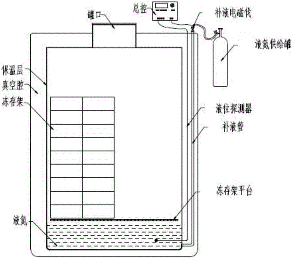
[0023] The purpose of the present invention is to overcome the above-mentioned shortcomings in the prior art, and to provide a gas-phase liquid nitrogen storage tank that can work normally for a long time without an external liquid nitrogen supply tank, thereby greatly reducing the evaporation of liquid nitrogen in the entire liquid nitrogen cryopreservation system High efficiency, greatly reducing the frequency of liquid nitrogen replenishment, while avoiding the chain reaction caused by the quality problems of the liquid nitrogen supply tank, and no need to spend rental fees, a new type of gas-phase liquid nitrogen biological storage tank that reduces the overall cost of use

Method used


Image

  • Gas phase liquid nitrogen biology storage tank
  • Gas phase liquid nitrogen biology storage tank
  • Gas phase liquid nitrogen biology storage tank

Examples


Embodiment Construction

[0035] In order to understand the technical content of the present invention more clearly, the following examples are given in detail.

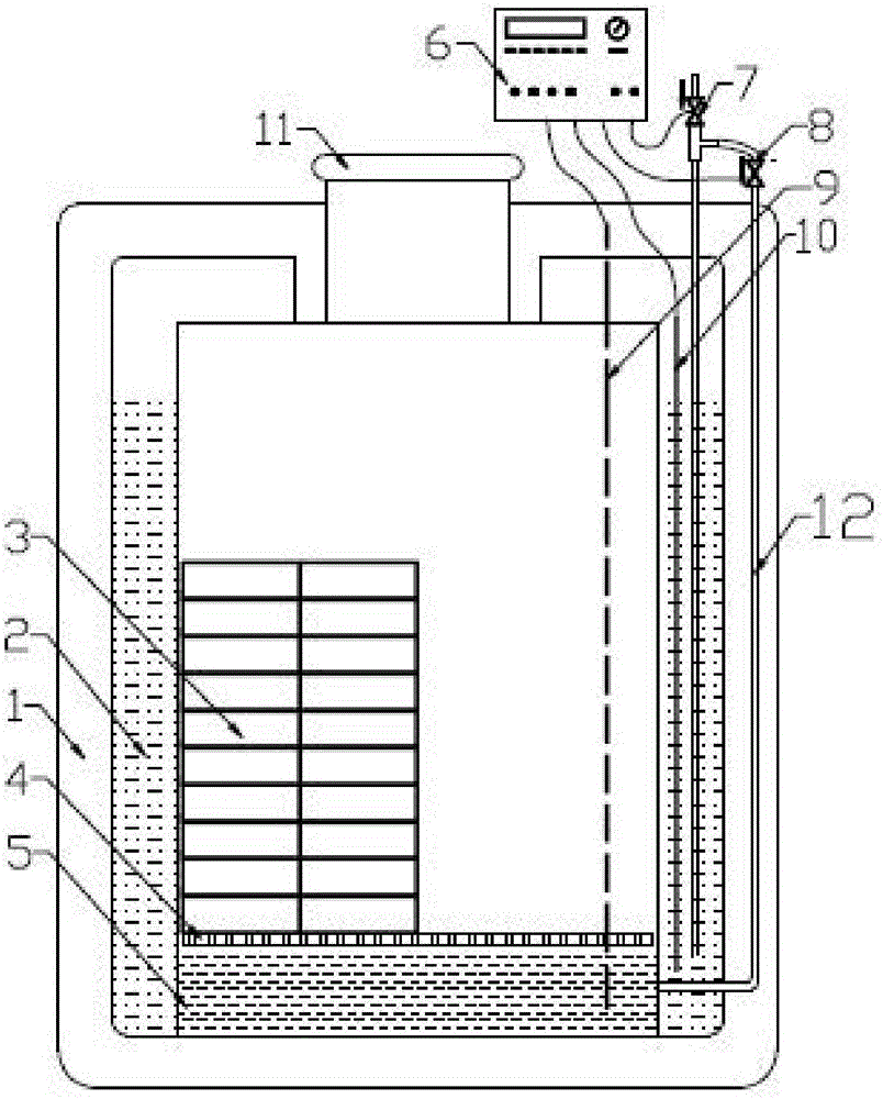
[0036] see figure 2 Shown is a schematic structural diagram of the gas-phase liquid nitrogen biological storage tank of the present invention.

[0037] In one embodiment, the gas-phase liquid nitrogen biological storage tank includes a vacuum tank wall 1, an inner cavity located in the vacuum tank wall 1, and a tank mouth 11 communicating with the inner cavity and the outside of the vacuum tank wall 1, the There is an inner cavity liquid nitrogen layer 5 at the bottom and a cryopreservation shelf platform 4 above the inner cavity liquid nitrogen layer 5 in the inner cavity of the inner cavity, and a cryopreservation shelf 3 is placed on the cryopreservation shelf platform 4, and the vacuum tank A liquid nitrogen storage chamber 2 is provided between the wall 1 and the inner cavity, and the liquid nitrogen storage chamber 2 communicates with...


PUM


Abstract

The invention relates to a gas phase liquid nitrogen biology storage tank and belongs to the technical field of biological medicines. The gas phase liquid nitrogen biology storage tank comprises a vacuum tank wall, an inner cavity located in the vacuum tank wall, and a tank opening for communicating the inner cavity and the outer side of the vacuum tank wall. The inner cavity is internally provided with an inner cavity liquid nitrogen layer located on the bottom, and a cryopreservation frame platform located above the inner cavity liquid nitrogen layer. A cryopreservation frame is placed on the cryopreservation frame platform. A liquid nitrogen storage cavity is arranged between the vacuum tank wall and the inner cavity. The liquid nitrogen storage cavity is communicated with the inner cavity through a liquid supplementing pipe, the liquid nitrogen capacity in a tank body is increased greatly, evaporation of liquid nitrogen in an inner cavity body is reduced, temperature uniformity in the tank body is also improved, the liquid nitrogen consumption amount is reduced, and thus the use cost is reduced wholly and greatly. Meanwhile, the number of times and the use frequency for replacing external liquid nitrogen tanks are reduced, and daily use and maintenance are more convenient. Moreover, the gas phase liquid nitrogen biology storage tank is simple in structure and also fairly wide in application range.

Description

technical field [0001] The invention relates to the technical field of biomedicine, in particular to the technical field of low-temperature storage, in particular to a gas-phase liquid nitrogen biological storage tank. Background technique [0002] At present, in the field of biological research and clinical treatment, relevant users use a large number of gas-phase liquid nitrogen biological storage tanks to store biological samples. Especially in cord blood banks, various stem cell banks, and immune cell banks, this equipment must be used to ensure the safe storage of cells. [0003] The gas-phase liquid nitrogen biological storage tank is a large stainless steel container, surrounded by a vacuum insulation layer, and externally connected to a liquid nitrogen supply tank. The liquid nitrogen in the gas-phase liquid nitrogen biological storage tank is continuously evaporated and cooled to ensure the low-temperature storage of biological samples. Its product quality requires...

Claims


Application Information

Patent Timeline
IPC IPC(8): B65D81/20
CPCB65D81/2069
Inventor 徐伟强
Owner 徐伟强
Learn More