Rotary multi-needlepoints electrostatic spinning device

An electrospinning, multi-needle-tip technology, applied in textiles and papermaking, filament/thread forming, fiber processing, etc., can solve the problems of great influence of diameter, equipment cost, increased complexity, instability, etc.

Inactive Publication Date: 2017-03-08
FUJIAN BEISIDA ENVIRONMENTAL PROTECTION INVESTMENT +1
View PDF0 Cites 7 Cited by
  • Summary
  • Abstract
  • Description
  • Claims
  • Application Information

AI Technical Summary

Problems solved by technology

Traditional electrospinning devices mainly use injection needles or capillary tubes as nozzles, and form a droplet meniscus under the extrusion of a syringe pump. The main reason is that they have a high aspect ratio and can better focus the electric field so that the The electric field strength is higher, which can better make the meniscus generate rheology and spray to form a jet; the use of similar capillaries and injection needles as nozzles simplifies the equipment required for electrospinning, but also introduces nozzles The problem of clogging, because the inner diameter of the electrospinning nozzle is generally at the level of 100 microns, once the clogging is not easy to deal with, especially when the needle nozzle of the array is introduced for large-scale electrospinning, it will seriously affect the behavior of multi-jet jetting and nanofibers. Uniformity; At the same time, a common disadvantage of capillary nozzles is that there will be solution backflow inside the hanging drop at the nozzle, and unstable solution backflow will affect the stability of the electrospinning tap-jet mode
In addition, the liquid supply rate has a great influence on the diameter of nanofibers produced by electrospinning. It is difficult for a general multi-nozzle electrospinning device to achieve the uniformity of multi-nozzle liquid supply. Detailed and complex flow channel design can be achieved, but The overall equipment cost and complexity are increased

Method used


Image

  • Rotary multi-needlepoints electrostatic spinning device
  • Rotary multi-needlepoints electrostatic spinning device
  • Rotary multi-needlepoints electrostatic spinning device

Examples


Embodiment Construction

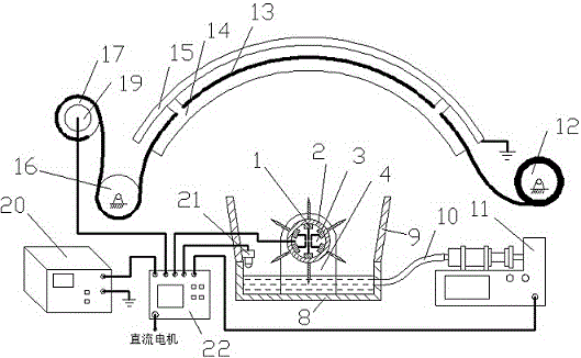
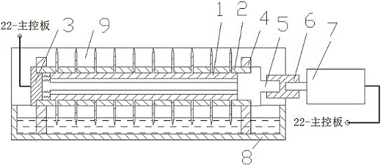
[0014] exist figure 1Among them, the needle point group (1) is fixedly connected with the sleeve (2), and the needle point protrudes from the outer surface of the sleeve (2) as a nozzle, and the needle point group (1) has a total of 6 sets of circumferences evenly on the sleeve (2); the electrode plate (3) Cooperate with one end of the sleeve (2), and the electrode plate (3) is designed with power supply lines, which are respectively connected to 6 sets of needle tip groups (1), and each set of lines is isolated from each other; the electrode plate (3) is designed with a lead The circuit is connected with the main control board (22) to realize independent power supply among different needle point groups (1); the liquid tank (8) is arranged directly under the sleeve (2) and is filled with spinning solution, and the liquid tank (22) has two The backflow plate (9) is installed on the side. When the DC motor (7) drives the sleeve (2) to rotate, the array of needle point groups (1)...


PUM

PropertyMeasurementUnit
diameteraaaaaaaaaa
diameteraaaaaaaaaa

Abstract

The invention discloses a rotary liquid-quenching batch electrostatic spinning device with a plurality of needlepoint group arrays, and the electrostatic spinning device is provided with a roller group and collection cloth that are used for batch collection for nanofibers. The electrostatic spinning device is provided with needlepoint groups, a sleeve, an electrode plate, a support, a rotary shaft, a coupler A, a DC (Direct Current) motor, a flume, a backflow plate, a solution guide pipe, a solution supply pump, a conveying roller, the collection cloth, a guide frame, an arc-shaped plate, a pressure roller, a collection roller, a coupler B, a roller motor, a high-voltage power supply, an infrared sensor and a main control board. Electrostatic spinning is carried out by introducing needlepoints, so that the solution backflow phenomenon and nozzle plugging are overcome, so as to reduce the critical starting voltage for spinning and improve the stability of jet flow of a spinning awl; the electrostatic spinning is carried out by using needlepoint group arrays, and the roller group and the collection cloth are combined as a collection device, thereby realizing batch manufacturing for the nanofibers and uniform non-woven fabric collection; solution is supplied in a way that the needlepoint groups rotate for quenching solution in the flume, so that the uniformity of solution supply can be realized, and the uniformity of diameters of the collected nanofibers is improved.

Description

technical field [0001] The invention relates to an electrostatic spinning device, in particular to a large-area, multi-jet spinning and collecting electrostatic spinning device with a multi-spinneret array. Background technique [0002] Electrospinning is a new technology that can easily produce nanofibers. In recent years, with the development of nanotechnology, electrospinning technology has also been fully studied and has been widely used in bioengineering, filter materials, chemical The fields of catalysis and flexible electronics. Electrospinning mainly uses an external electric field to polarize the surface of the solution to generate surface charges. The surface charges stretch the solution under the action of the electric field to form a Taylor cone. Continuously increasing the effect of the electric field will generate a jet from the tip of the Taylor cone, and the jet whips in space. The nanofibers are finely refined by dynamic motion, and finally deposited on the...

Claims


Application Information

Patent Timeline
Patent Type & Authority Applications(China)
IPC IPC(8): D01D5/00
Inventor 郑煜铭郑志烨吴仁香陈澍王进兴
Owner FUJIAN BEISIDA ENVIRONMENTAL PROTECTION INVESTMENT
Why Eureka
Try Eureka