Gas detector and absorption pool thereof

A technology of gas detectors and absorption cells, applied in instruments, measuring devices, scientific instruments, etc., can solve problems such as not easy to carry, complex structure, large distance between optical transmitter and optical receiver, etc., to save space and ensure accuracy Effect

Active Publication Date: 2017-03-08
GL TECH CO LTD
View PDF12 Cites 8 Cited by
  • Summary
  • Abstract
  • Description
  • Claims
  • Application Information

AI Technical Summary

Problems solved by technology

[0004] However, since the light entrance structure (light entrance) of the incident light and the light exit structure (light exit) of the outgoing light in the above-mentioned prior art are distributed on opposite sides in the radial direction of the reflector near the light source end, this leads to The distance between the light entrance structure (light entrance) of the incident light and the light exit structure (light exit) of the outgoing light is too large, so that the distance between the light transmitter and the light receiver is set too large, resulting in the gas detection equipment in the path The size in the direction is too large, so that the structure of the detection equipment has problems such as large volume, heavy weight, and complicated structure, which cannot be used in extreme environments (high temperature vibration), and is not easy to carry.

Method used


Image

  • Gas detector and absorption pool thereof
  • Gas detector and absorption pool thereof
  • Gas detector and absorption pool thereof

Examples


Embodiment Construction

[0022] Embodiments of the present invention will be further described below in conjunction with the accompanying drawings.

[0023] Gas Detector Example

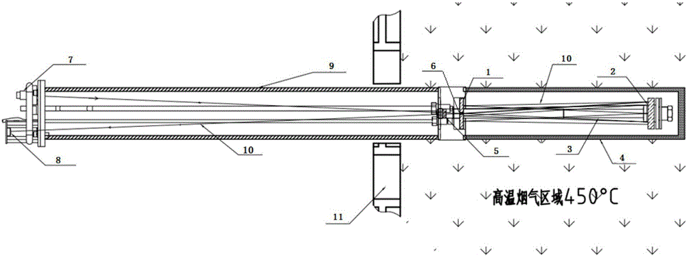
[0024] figure 1 It is a schematic diagram of the basic structure of a gas detector of the present invention, which includes an absorption cell and an optical transmitter 7 and an optical receiver that are arranged on the left side of the absorption cell on the gas detector and provided with the left end of the optical path cavity for light to pass through. 8, and the outside of the optical path cavity is wrapped with a thin-walled supporting steel pipe 9.

[0025] The gas detector in this embodiment also includes a deflection prism 5 arranged at the right end of the optical path cavity through which light passes.

[0026] The absorption cell of the gas detector in this embodiment includes the absorption cell cavity and the reflector at the near light source end, the reflector at the far light source end, the light incident...


PUM


Abstract

The invention relates to a gas detector and an absorption pool thereof. The absorption pool is a plano-concave optical resonant cavity; near end reflecting points and far end reflecting points formed by light paths on a plane reflecting mirror and a concave reflecting mirror are all in circumferential distribution around an optic axis of the resonant cavity; a light inlet structure of incident light and a light outlet structure of emergent light are both arranged on the plane reflecting mirror; the positions of the light inlet structure and the light outlet structure can be arranged on a coincident reflecting point with different reflecting sequences and coincident positions, and can also be two mutually approaching points in the near end reflecting points. Through such arrangement, a gap between the light inlet structure of the incident light and the light outlet structure of the emergent light can be as small as possible. When the absorption pool is used, the dimension of the gas detector in a radial direction becomes small, the space is saved, the structure miniaturization is realized, and the carrying is convenient; in addition, the optical path of light rays becomes long in the optical resonant cavity with small volume, so that the subsequent gas detection work is facilitated.

Description

technical field [0001] The invention relates to the technical field of gas detection, in particular to a gas detector and an absorption pool thereof. Background technique [0002] Existing gas concentration detection devices, such as the Chinese patent document "A Portable Pollution Gas Concentration Detection Device" with the notification number CN 205593914 U, include an absorption pool, a light transmitter and a light receiver arranged on the same side of the absorption pool, and an optical The detection device connected to the receiver, wherein the absorption pool includes the absorption pool cavity for the gas to be measured to enter, and the absorption pool cavity is equipped with a near light source end reflector, a far light source end reflector, a near light source end reflector, a far light source end reflector, and a left and right distribution in the absorption pool cavity. The reflector at the light source end actually constitutes an optical resonant cavity. The...

Claims


Application Information

Patent Timeline
Patent Type & Authority Applications(China)
IPC IPC(8): G01N21/03
CPCG01N21/03G01N21/0303Y02A50/20
Inventor 赵彤宇刘鑫鑫石云鹏周慧锋詹放易
Owner GL TECH CO LTD
Why Eureka
Try Eureka