Rotary cutting cutter

A technology of knife and inner knife, which is applied in the field of medical surgical biopsy sampling equipment, can solve the problems of cumbersome manual operation, heavy overall weight, and low efficiency, and achieve the effect of ensuring operation safety, high motion stability, and high rotary cutting efficiency

Active Publication Date: 2017-03-15
CHONGQING XISHAN SCI & TECH
View PDF14 Cites 1 Cited by
  • Summary
  • Abstract
  • Description
  • Claims
  • Application Information

AI Technical Summary

Problems solved by technology

[0002] During the operation, the doctor usually uses a rotary cutter to perform the operation when sampling the living body of the patient or removing the lesion tissue. The cutters used for rotary cutting surgery on the market today usually include an inner knife and an outer knife that is covered with the inner knife. There is a sampling groove along the radial direction at the front end of the knife base; after puncturing, the tissue is sucked into the sampling groove under negative pressure, at this time, the inner knife rotates forward to cut off the tissue and accommodate it into the front end of the inner knife; of course, the inner knife will Close the sampling slot at the front end, puncture to the position and then back out of the sampling slot, the position and distance of the back up are determined according to the amount of sampling, negative pressure is applied during the back up process, and then rotary cutting sampling is performed; existing In the technology, a separate and independent drive mechanism is used to drive the inner knife to rotate and axially translate. The motor drives the inner knife to rotate, and at the same time pushes the inner knife to slide axially through the push rod, thereby realizing the combination of rotation and translation to realize rotary cutting. The driving methods of the push rod include electric and manual. Manual operation is cumbersome and the efficiency is not high. When the electric drive is driven, a reducer is required to slowly push the inner knife, which makes the structure of the rotary cutting tool complex, and the overall weight is relatively heavy. The driving mechanism for the rotation and translation of the inner knife is prone to interference, resulting in the locking of the inner knife, resulting in unstable operation of the rotary cutting tool, which is likely to bring risks to the operation

Method used


Image

  • Rotary cutting cutter
  • Rotary cutting cutter
  • Rotary cutting cutter

Examples


Embodiment Construction

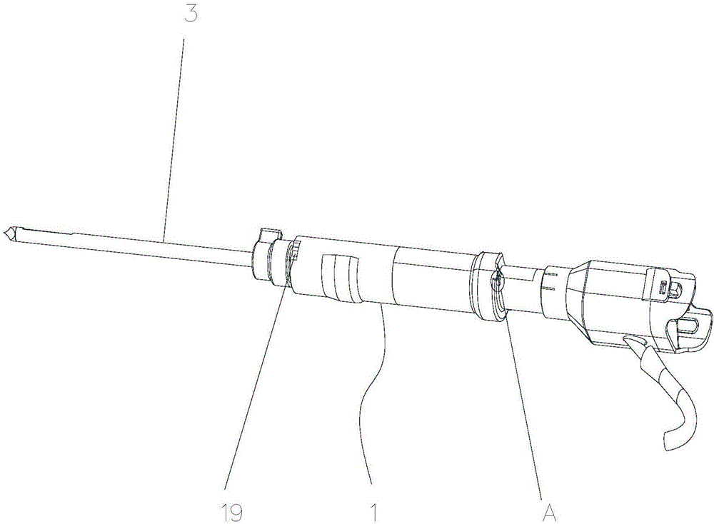
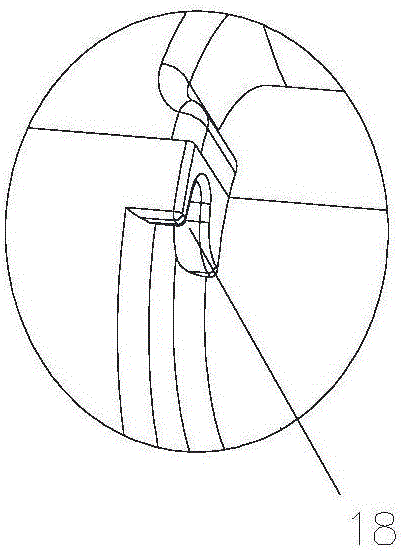
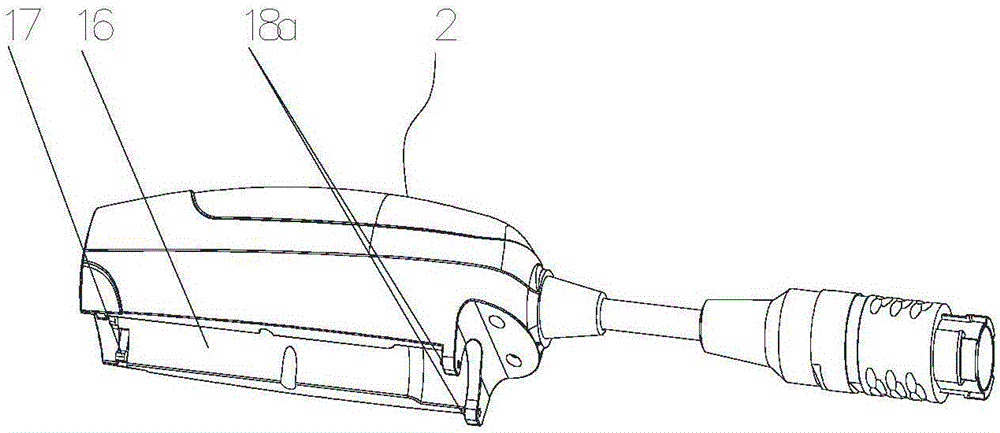
[0024] figure 1 It is a structural schematic diagram of the present invention, figure 2 for figure 1 Enlarged view of A in the middle, image 3 It is a structural representation of the handle in the present invention, Figure 4 It is a schematic diagram of the structure after installation of the present invention, Figure 5 for Figure 4 Enlarged picture at B in middle, Figure 6 for Figure 5 The magnified picture at C in the middle, Figure 7 It is a schematic structural view of the rotary drive and the translational drive in the present invention, Figure 8 for Figure 7 As shown in the figure, the rotary cutting tool 1 in this embodiment includes an outer knife 3 with a sampling groove 5 at the front end, an inner knife 4 sleeved on the outer knife 3 and a knife fixedly connected to the outer knife 3 The handle 15 also includes a rotary drive member 6 that is axially slidably engaged with the inner knife 4 in the circumferential direction and a translational driv...


PUM


Abstract

The invention discloses a rotary cutting cutter. The rotary cutting cutter comprises an outer cutter, an inner cutter, a rotation driving piece and a translational motion driving piece, wherein a sampling groove is formed in the front end of the outer cutter, the outer cutter sleeves the inner cutter; the rotation driving piece is in axial sliding fit with circumferential transmission of the inner cutter, and the translational motion driving piece is matched with the inner cutter through a lead screw structure; the rotation driving piece is used for driving the inner cutter to rotate, a rotating speed difference is formed by the rotation driving piece and the translational motion driving piece, and then axial motion of the inner cutter is driven through the rotating speed difference to realize sampling of the sampling groove; the rotation and translational motion of the inner cutter are driven in a differential driving manner through the rotation driving piece and the translational motion driving piece, complex and relatively heavy integral structure of the cutter caused by the fact that a speed reducer is needed to realize speed reduction output is avoided, the rotation and translational motion are guaranteed to be unlikely to intervene by setting a differential driving gear, the rotary cutting efficiency of operation is high, the motion stability of operating assemblies is high, and the safety of the operation is guaranteed.

Description

technical field [0001] The invention relates to a medical operation biopsy sampling instrument, in particular to a rotary cutter. Background technique [0002] During the operation, the doctor usually uses a rotary cutter to perform the operation when sampling the patient's body or removing the lesion tissue. The cutter used for the rotary cutter on the market today usually includes an inner knife and an outer knife that is covered with the inner knife. There is a sampling groove along the radial direction at the front end of the knife base; after puncturing, the tissue is sucked into the sampling groove under negative pressure, at this time, the inner knife rotates forward to cut off the tissue and accommodate it into the front end of the inner knife; of course, the inner knife will Close the sampling slot at the front end, puncture to the position and then back out of the sampling slot, the position and distance of the back up are determined according to the amount of samp...

Claims


Application Information

Patent Timeline
Patent Type & Authority Applications(China)
IPC IPC(8): A61B10/02
CPCA61B10/0233A61B10/0275A61B10/0283Y02W30/62
Inventor 郭毅军张金彬李洪远杨永波
Owner CHONGQING XISHAN SCI & TECH
Why Eureka
Try Eureka