
Arc pressure distribution measuring device and method based on graph phase centered short-time arcing

An arc pressure and measuring device technology, applied in arc welding equipment, manufacturing tools, welding equipment, etc., can solve the problems of inability to accurately measure the distance from the arc pressure distribution, the deformation of the electrode plate hole, etc., to achieve accurate measurement results and reduce guide The effect of hole deformation and maintaining measurement accuracy

Active Publication Date: 2017-03-15
TIANJIN UNIV
View PDF4 Cites 7 Cited by
  • Summary
  • Abstract
  • Description
  • Claims
  • Application Information

AI Technical Summary

Problems solved by technology

[0006] The technical problem to be solved by the present invention is that, firstly, due to the long-time measurement in the sensor continuous measurement method, the problem of deformation of the plate hole caused by arc heat; For the problem of arc pressure distribution, a device and method for measuring arc pressure distribution based on graph-based relatively short-time arcing is provided, and the measurement device is optimized to make the measurement operation easier

Method used


Image

  • Arc pressure distribution measuring device and method based on graph phase centered short-time arcing
  • Arc pressure distribution measuring device and method based on graph phase centered short-time arcing
  • Arc pressure distribution measuring device and method based on graph phase centered short-time arcing

Examples


Embodiment Construction

[0026] In order to further understand the invention content, characteristics and effects of the present invention, the following examples are given, and detailed descriptions are as follows in conjunction with the accompanying drawings:

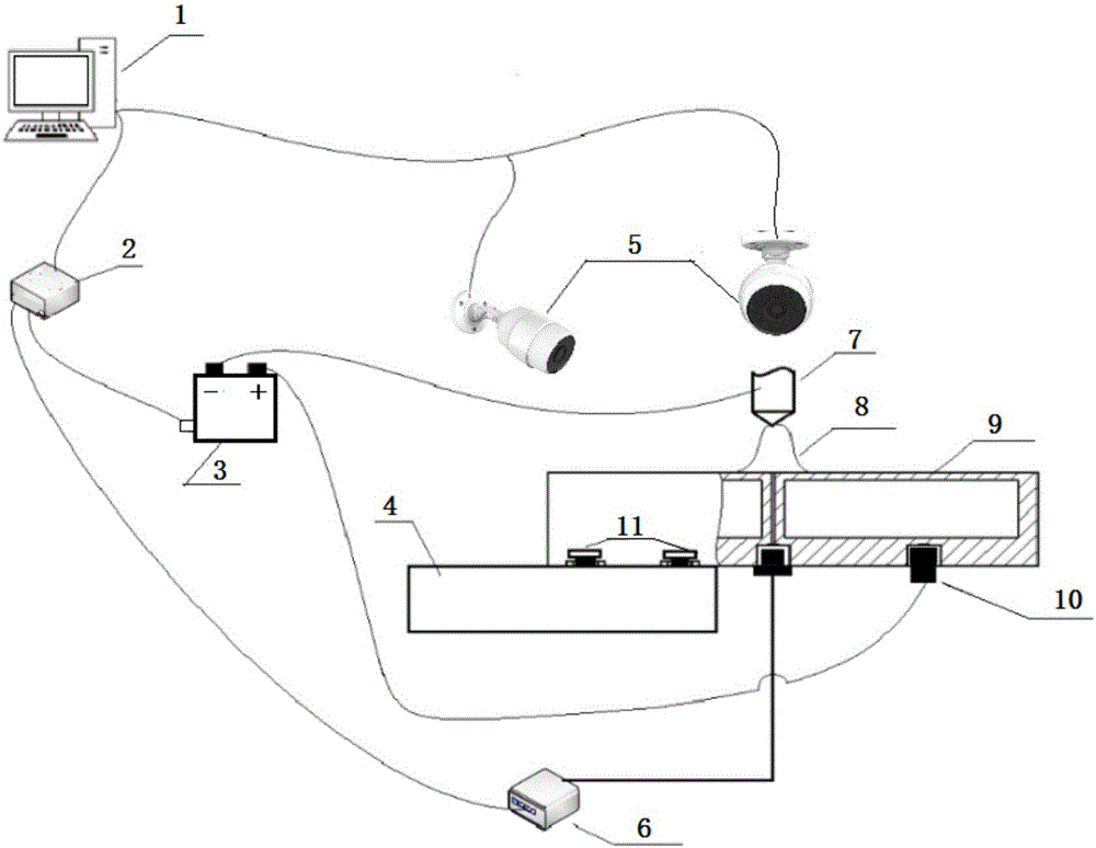
[0027] Such as figure 1 As shown, this embodiment discloses a device for measuring arc pressure distribution based on graph relative short-term arc starting, including a computer system 1, a data acquisition controller (DAQ) 2, a controllable welding power source 3, and a high-precision manual translation platform 4. Camera 5, pressure sensor 6, welding torch 7, water-cooled plate 9, electrode 10. Among them, the data acquisition controller (DAQ) 2 adopts the NI USB-6002 type; the high-precision manual translation stage 4 adopts the PP160-25H type, and its table size is 110m*80mm. The stroke is 25mm, the minimum scale is 0.01mm, the minimum adjustment is 2μmm, the guide rail is a high-precision ultra-thin linear slide rail, the load is 20kg,...


PUM

PropertyMeasurementUnit
Diameteraaaaaaaaaa

Abstract

The invention belongs to the field of welding arc pressure measuring, and discloses an arc pressure distribution measuring device and method based on graph phase centered short-time arcing. A computer system is connected with a data collection controller; the data collection controller is connected with a pressure sensor and a controllable welding power source which is connected with a welding torch and an electrode, arcs sent out by the welding torch are aligned with a guide hole of a water cooling pole plate, and the electrode is connected with the water cooling pole plate; the pressure sensor is connected to the lower end of the guide hole; the water cooling pole plate is fixed to a high-precision manual transverse moving table; two cameras connected to the computer system are aligned with the guide hole in two vertical directions at the level to carry out shooting; during measuring, the controllable welding power source is controlled to discharge for 0.5 second to 2 seconds, and when the arcs are stabilized, the cameras carry out shooting; the air pressure in the guide hole is changed and is transmitted through the pressure sensor, and data are recorded; the position of the guide hole is subject to fine adjustment through the high-precision manual transverse moving table, and the arc pressure of the continuous measuring point in one direction is measured, the data are collected and arranged, and the arc pressure distribution is obtained.

Description

technical field [0001] The invention relates to the field of welding arc pressure measurement, in particular to a device and method for measuring arc pressure distribution based on image pairing and short-time arc starting. Background technique [0002] Arc pressure is an important parameter in the welding process, which directly affects the stability of the welding process, the formation of weld gas impurities, defects, weld penetration and forming, etc. When a larger current is used, the arc pressure applied to the molten pool is an important parameter to determine the penetration depth of the weld bead. A higher arc pressure is required to obtain a certain penetration depth, but too high arc pressure may cause welding defects such as penetration. It is difficult to strictly distinguish various arc forces in actual measurement. Arc forces mainly include arc static pressure (electromagnetic contraction force), arc dynamic pressure (plasma flow force), blasting force, spot ...

Claims


Application Information

Patent Timeline
IPC IPC(8): B23K9/095
CPCB23K9/0956
Inventor 刘祖明王绍磊伊松刘知易邱嘉玉
Owner TIANJIN UNIV
Learn More