punching machine

A stamping machine and frame technology, applied in the field of stamping machines, can solve the problems of increased gap between eccentric wheel and brake pad, fast downward speed of punch, easy wear of brake wheel, etc., achieve uniform line contact force, improve strength, The effect of extending the service life

Active Publication Date: 2018-05-29
丁乃祥
View PDF11 Cites 4 Cited by
  • Summary
  • Abstract
  • Description
  • Claims
  • Application Information

AI Technical Summary

Problems solved by technology

In addition, when the tooth thickness is excessively thinned after tooth wear, the tooth will also break under normal working conditions.
[0004] When the punching machine is working, the punch of the punching machine goes down very fast and has a great impact force. Nowadays, an eccentric brake wheel is usually installed on the crankshaft to slow down. It is also used to ensure the normal clutch, but the brake wheel is easy to wear, and the eccentric wheel and the brake The gap between the plates increases, reducing the braking effect

Method used


Image

  • punching machine
  • punching machine
  • punching machine

Examples


Embodiment Construction

[0022] Embodiments of the present invention are further described below in conjunction with accompanying drawings:

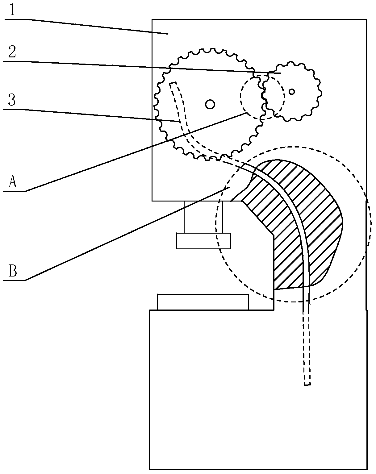
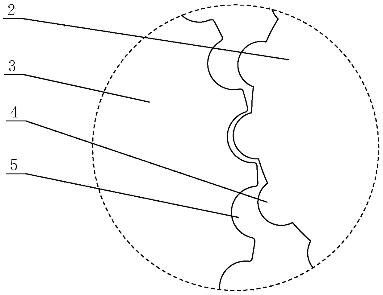
[0023] Such as Figure 1-Figure 5 As shown, the stamping machine of the present invention includes a driving gear 2 and a driven gear 3, the driving gear 2 is connected with the motor shaft through a transmission device, the driven gear 3 is fixed on the crankshaft, and the driving gear 2 passes through the driven gear 3 Mesh to transmit power, the working surface of the gear tooth 4 on the driving gear 2 is arc-shaped, and the driven gear 3 is provided with an arc-shaped groove 5. When the groove 5 meshes with the gear tooth 4, the inner surface of the groove 5 is in line with the The outer surfaces of the gear teeth 4 are closely fitted together.

[0024] Working principle and process:

[0025] When working, when the groove 5 meshes with the gear tooth 4, the inner surface of the groove 5 is closely matched with the outer surface of the gear tooth 4, and the...


PUM


Abstract

The invention relates to a stamping machine, and belongs to the mechanical field. The stamping machine comprises a drive gear and a driven gear, wherein the drive gear is connected with a rotary shaft of a motor through a transmission device; the driven gear is fixed on a crankshaft; the drive gear transfers power in a manner of being engaged with the driven gear; the working surfaces of gear teeth on the drive gear are arc-shaped; arc-shaped grooves are arranged in the driven gear; the inner surfaces of the grooves are in close fit with the outer surfaces of the gear teeth when the grooves are engaged with the gear teeth. The gear teeth have the arc surfaces, the gears are engaged through the arc surfaces, the gear teeth form contact through the arc surfaces during the engagement process, and stresses on the parts of the gear teeth are uniform to prevent hard collision among the teeth.

Description

technical field [0001] The invention relates to a stamping machine, which belongs to the field of machinery. Background technique [0002] A stamping press is a stamping press. In national production, the stamping process has the advantages of saving materials and energy, high efficiency, low technical requirements for operators, and the ability to produce products that cannot be achieved by mechanical processing through various mold applications. Its use is more and more extensive. [0003] The design principle of the punching machine is to convert circular motion into linear motion. The shaft of the main motor drives the driving gear through the transmission device. The driving gear and the flywheel are meshed for transmission. The slider and the flywheel drive the crankshaft to rotate, and the crankshaft drives the punch to move in a straight line. The size of the flywheel is relatively large, so it is generally made by casting. The strength of cast iron itself is poor...

Claims


Application Information

Patent Timeline
Patent Type & Authority Patents(China)
IPC IPC(8): B30B15/00B30B15/04B30B15/28B30B1/26
Inventor 丁乃祥
Owner 丁乃祥
Why Eureka
Try Eureka