
Waterproof and drainage system and construction method of low-medium radioactive waste grotto type disposal site

A technology of drainage system and construction method, applied in the field of nuclear power, can solve problems such as ineffective water isolation, and achieve the effect of reducing nuclear radiation damage

Active Publication Date: 2017-03-15
CHANGJIANG SURVEY PLANNING DESIGN & RES
View PDF9 Cites 5 Cited by
  • Summary
  • Abstract
  • Description
  • Claims
  • Application Information

AI Technical Summary

Problems solved by technology

[0013] The purpose of the present invention is to overcome the inadequacies of the above-mentioned existing background technology, and the single concrete structure existing in the existing waterproof and drainage measures for low and medium level radioactive waste cavern disposal sites cannot effectively prevent water, and can only slow down and reduce pollutants from protection. The release speed and magnitude of the facility, as well as the radiation damage caused by grouting and vibrating construction, and other related issues, have developed a low-level and intermediate-level radioactive waste cavern-type disposal site waterproof and drainage system and construction method, which can meet the requirements of the disposal site within the design period. Strict requirements for safety and durability

Method used


Image

  • Waterproof and drainage system and construction method of low-medium radioactive waste grotto type disposal site
  • Waterproof and drainage system and construction method of low-medium radioactive waste grotto type disposal site
  • Waterproof and drainage system and construction method of low-medium radioactive waste grotto type disposal site

Examples


Embodiment Construction

[0066] The present invention will be described in further detail below in conjunction with the accompanying drawings and embodiments, but these embodiments should not be construed as limiting the present invention.

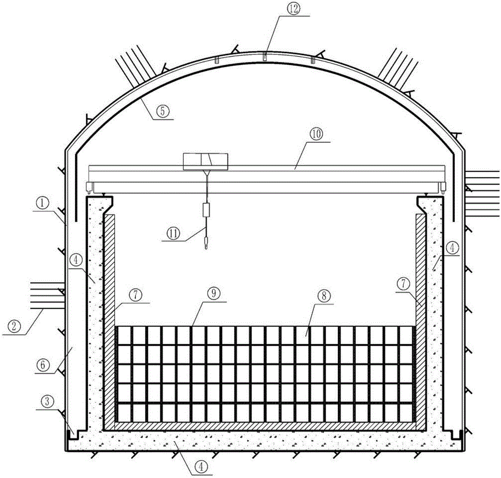
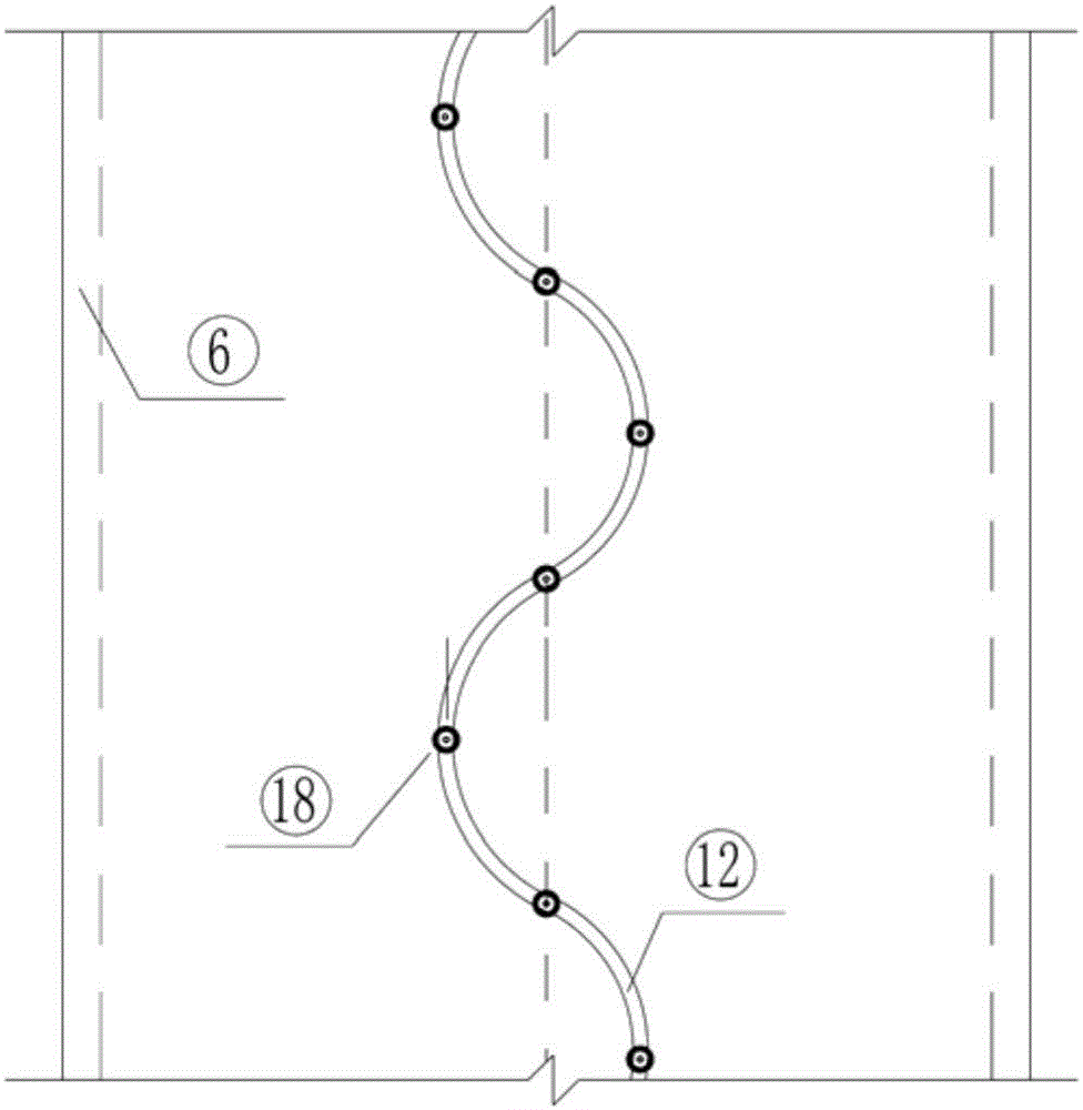
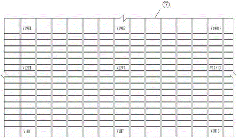
[0067] The waterproof and drainage system of the cavern type disposal site for low and intermediate radioactive waste of the present invention is located in the cavern, the cavern inner wall is provided with cave wall spraying protection 1, and the cavern inner wall fissure is provided with fissure sealing 2. refer to Figure 1 ~ Figure 3 , the system includes the anti-seepage side wall and the bottom plate 4 of the U-shaped concrete frame structure, and the two sides of the anti-seepage side wall and the bottom plate 4 are out of contact with the wall of the excavated cavern, so as to avoid secondary cracking of the concrete structure caused by the deformation of the rock mass. The frame structure is used as a storage space for radioactive waste barrels, and as a...


PUM


Abstract

The invention discloses a waterproof and drainage system and a construction method of a low-medium radioactive waste grotto type disposal site. The waterproof and drainage system comprises a seepage-preventing side wall and base plate and a waterproof ceiling, wherein the seepage-preventing side wall and base plate is located in a grotto and is U-shaped, the waterproof ceiling is in an inverted-U shape, the waterproof ceiling and the seepage-preventing side wall and base plate are in a buckled-closed state, a clay side wall and base plate is arranged on the inner side of the seepage-preventing side wall and base plate, waste buckets are arranged inside the clay side wall and base plate, an open water draining drain is formed in the outside of the seepage-preventing side wall and base plate and located below the end of the waterproof ceiling, a crane beam is arranged at the top of the seepage-preventing side wall and base plate and located inside the waterproof ceiling, a crane, a grouting pipeline and a spray nozzle are arranged on the crane beam, and a top arched embedded pipeline is arranged in a grotto top arch. The problem that a grotto protection structure existing in an existing project measure is simple and can only retard and reduce the release speed and amplitude of pollutants from a protective facility is well solved, and a series of problems including personal radiation injury and the like due to the grouting and vibrating construction in gaps among the waste buckets are solved.

Description

technical field [0001] The invention relates to nuclear power technology, in particular to a water-proof and drainage system and a construction method for a cavern type disposal site of low and intermediate radioactive waste. Background technique [0002] With the continuous development of the nuclear industry, a large amount of radioactive waste is bound to be produced. Effective and proper disposal of radioactive waste is related to the sustainable development of the nuclear industry and the safety of human living environment. [0003] Relevant regulations stipulate that nuclear waste can be divided into low, medium and high radioactive waste according to the level of radioactive activity. Among them, high-level radioactive waste is generally disposed of in deep geological layers, which is still in the research stage internationally, and high-level radioactive waste is in a temporary storage state. Low- and intermediate-level wastes are generally disposed of near the surf...

Claims


Application Information

Patent Timeline
Patent Type & Authority Applications(China)
IPC IPC(8): E21D11/38E21F16/00
CPCE21D11/381E21D11/383E21F16/00
Inventor 杨启贵施华堂李洪斌樊少鹏周述达王汉辉张国强刘瑞懿于习军刘权庆黄小艳肖碧喻飞金乾张涛苏毅
Owner CHANGJIANG SURVEY PLANNING DESIGN & RES
Learn More