Method and device for accurate measurement of large-range displacement and application
An accurate measurement, large-scale technology, applied in the direction of measurement device, optical device, height/level measurement, etc., can solve the problem of small measurement range, and achieve the effect of improving work efficiency, high precision, and extending the range of distance measurement.
- Summary
- Abstract
- Description
- Claims
- Application Information
AI Technical Summary
Problems solved by technology
Method used
Image
Examples
Embodiment approach
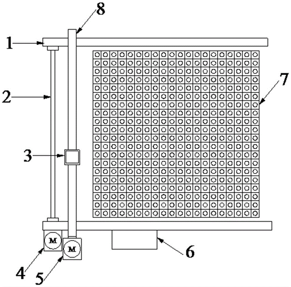
[0055] The position guide includes a photosensitive device arranged in the large space plane range to capture the light signal, and the small space plane range is that a single photosensitive device can perceive the light signal in the measured space plane range. the range of the signal;
[0056] The area CCD element 3 can completely cover the photosensitive device in a certain way, so that the relative position between the area CCD element 3 and the photosensitive device remains unchanged in the covering state;
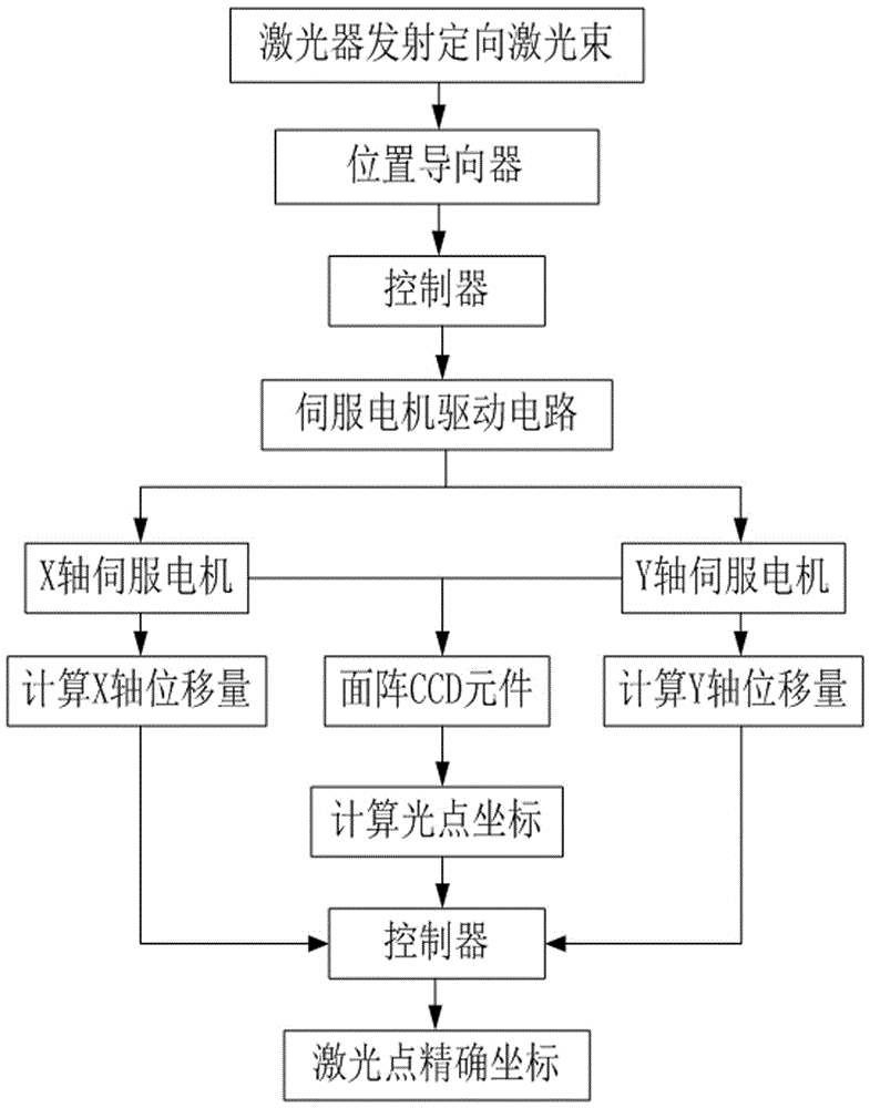
[0057] When the area array CCD element 3 moves to cover the photosensitive device in a predetermined manner, the position where the optical signal is perceived by a certain photosensitive point on the area array CCD element 3 is the precise position of the optical signal .
[0058] Using this embodiment, the displacement of the target to be measured between two different accurate positions before and after is calculated by summing the displacement of the area array ...
specific Embodiment approach 2
[0062] As a preferred embodiment, the position guide includes a plurality of photosensitive devices, and the photosensitive devices are uniformly arranged as photosensitive units to form a photosensitive unit matrix 7, and the photosensitive unit matrix 7 can perceive the light in the measured space plane. The range of the signal is the range of the large spatial plane.
[0063] Specifically, the photosensitive device is a square photoresistor, photodiode or phototransistor, and adjacent photosensitive devices are closely arranged, and the sensing of the light signal is realized through a monitoring circuit.
[0064] Specifically, a transmission mechanism driven by a servo motor is provided on the side of the photosensitive cell matrix 7, and the transmission mechanism drives the area array CCD element 3 to move parallel to the photosensitive cell matrix 7 to cover the photosensitive cells that perceive the optical signal. device;
[0065] The plane displacement of the area a...
specific Embodiment approach 3
[0067] As another preferred embodiment, the measured spatial plane is perpendicular to the emission direction of the optical signal, and the spatial displacement of the target to be measured is calculated by the following method:
[0068] Measuring the time difference of the optical signal from the laser to the position guide before and after the movement of the target to be measured, and calculating the displacement of the target to be measured perpendicular to the measured space plane according to the speed of light by the displacement-time formula, The spatial displacement of the target to be measured is obtained by adding it to the displacement of the target to be measured on the measured space plane.
PUM
 Abstract
Description
Claims
Application Information
 - R&D
- Intellectual Property
- Life Sciences
- Materials
- Tech Scout
- Unparalleled Data Quality
- Higher Quality Content
- 60% Fewer Hallucinations
Browse by: Latest US Patents, China's latest patents, Technical Efficacy Thesaurus, Application Domain, Technology Topic, Popular Technical Reports.
© 2025 PatSnap. All rights reserved.Legal|Privacy policy|Modern Slavery Act Transparency Statement|Sitemap|About US| Contact US: help@patsnap.com


