
A cage type hyperbolic spring structure and socket

A spring structure, hyperbolic technology, applied in the direction of spring, spring/shock absorber, spring/shock absorber manufacturing, etc., can solve the problems of large insertion force, poor tensile resistance, large insertion force, etc., to reduce elasticity Space for deformation, prolonging the decay time, and ensuring the effect of stable contact

Active Publication Date: 2018-06-29
李慧敏
View PDF4 Cites 0 Cited by
  • Summary
  • Abstract
  • Description
  • Claims
  • Application Information

AI Technical Summary

Problems solved by technology

[0005] 1. The contact resistance of the socket method is large, and the tensile strength is poor. The front and rear sleeves are easily separated from the pressure point by the tension, causing connection failures and accidents; 2. The structure is complex, there are many combined parts, and the volume cannot be further reduced, which is not conducive to miniaturization 1. Intensive development; 3. Complex processing technology and high precision requirements, resulting in low product qualification rate and high cost; 4. The elastic metal wire cannot be very thick in a limited space, making it difficult for each wire to withstand the impact of a large current ;5. The broken wire of the elastic metal wire is unavoidable during use; 6. The insertion force is large, because the copper wire is fixed at both ends of the thin-walled tube and cannot be moved, resulting in a large insertion force;

Method used


Image

  • A cage type hyperbolic spring structure and socket
  • A cage type hyperbolic spring structure and socket
  • A cage type hyperbolic spring structure and socket

Examples


Embodiment Construction

[0026] In order to enable those skilled in the art to better understand the solutions of the present invention, the following will clearly and completely describe the technical solutions in the embodiments of the present invention in conjunction with the drawings in the embodiments of the present invention. Obviously, the described embodiments are only It is an embodiment of a part of the present invention, but not all embodiments. Based on the embodiments of the present invention, all other embodiments obtained by persons of ordinary skill in the art without making creative efforts shall fall within the protection scope of the present invention.

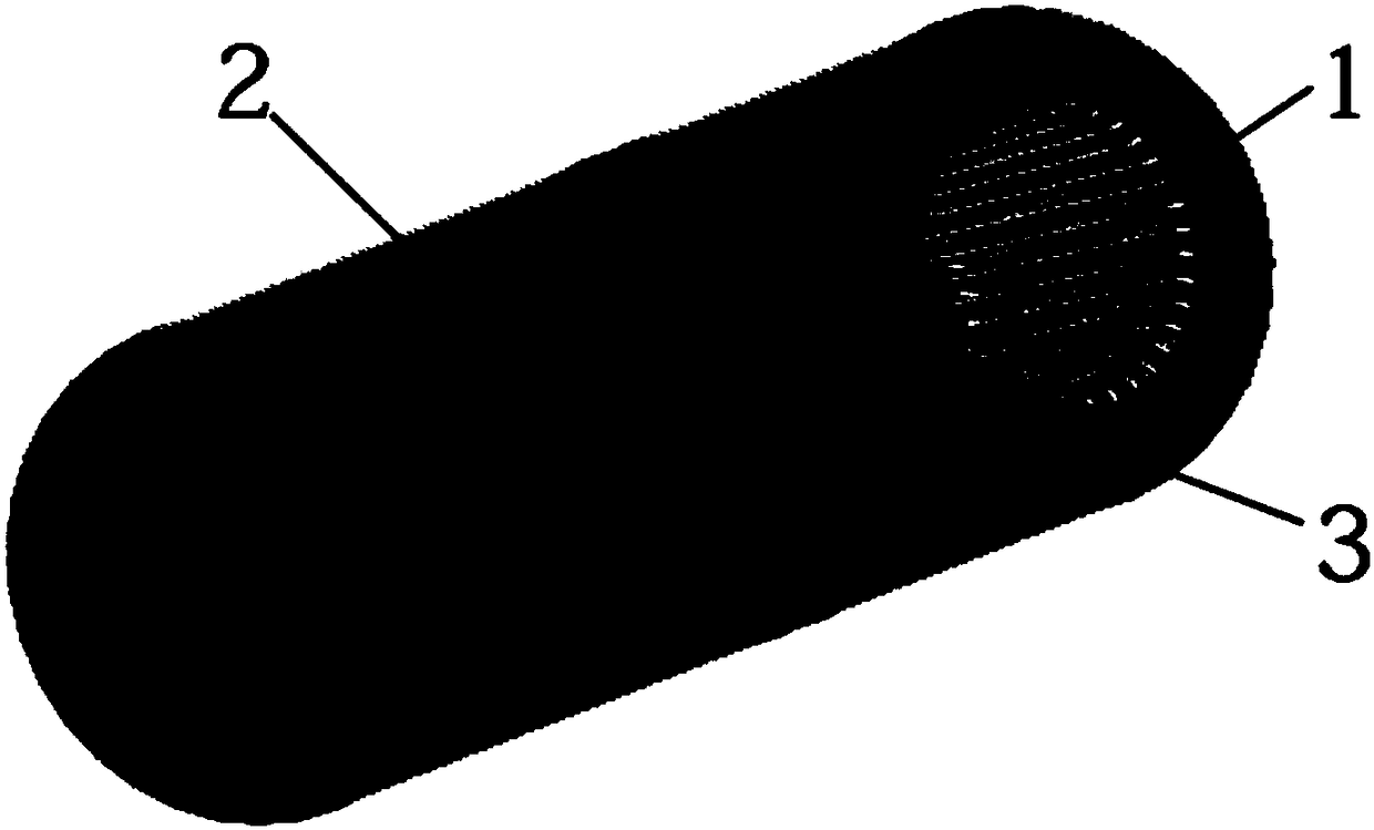
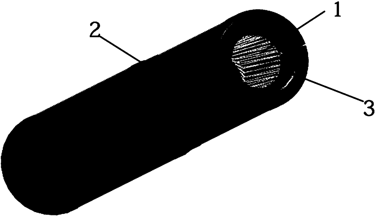
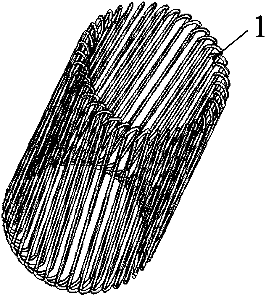
[0027] A cage type hyperbolic spring structure is provided in an embodiment of the present invention, such as figure 1 , figure 2 As shown, applied to jack terminals, the cage type hyperbolic spring structure includes a plurality of copper hyperbolic springs wound into a closed cylindrical ring structure 1 by laser spot welding, a...


PUM


Abstract

The embodiment of the invention discloses a cage type hyperbolic spring structure and a socket. The cage-type hyperbolic spring structure of the embodiment of the present invention is applied to the socket terminal, and the cage-type hyperbolic spring includes a plurality of copper hyperbolic column-shaped oblique springs that are circularly wound into a closed cylindrical ring structure by laser spot welding, and Machined body, the cylindrical annular spring structure is inserted into the machined body, and then the end of the thin-walled tube is riveted obliquely to ensure that the cylindrical oblique spring does not fall off during the insertion and removal of the male and female terminals. At the same time, it can also be used The method of assembly is to install an elastic C ring at the end of the thin-walled tube to compress it. In the embodiment of the present invention, the positive pressure of the male and female terminals is ensured during the mating process, which can ensure their stable contact under the condition of super high current, and each copper wire produces elastic deformation instead of plastic deformation during the compression process, which improves The service life of the product is extended, thereby prolonging the time for the spring to decay. At the same time, the hyperbolic spring structures can overlap each other during the compression process, thereby reducing the elastic deformation space of the spring, thereby ensuring a smaller volume.

Description

technical field [0001] The invention relates to the technical field of sockets, in particular to a cage type hyperbolic spring structure and a socket. Background technique [0002] At present, with the development of the electric vehicle industry, due to the need to use a larger current, the product has higher requirements for the jack, for example, a lower plug force to meet people's daily frequent charging and plugging needs; Contact resistance to reduce temperature rise caused by high current, etc. [0003] At present, the existing electrical connector contacts have single-leaf rotary hyperboloid wire spring jacks, and the single-leaf rotary hyperboloid wire spring jacks are evenly enveloped by a group of elastic metal wires arranged in a single-leaf rotary hyperboloid structure. On the surface of the pin inserted into it, it belongs to the multi-wire envelope contact. The jack contact with this wire spring structure is composed of four parts: inner sleeve, outer sleeve,...

Claims


Application Information

Patent Timeline
Patent Type & Authority Patents(China)
IPC IPC(8): H01R13/187
CPCH01R13/187H01R2201/26H01R2101/00F16F1/128F16F1/025F16F1/045F16F2226/048F16F2224/02H01R13/2407H01R24/58H01R2103/00
Inventor 冯纪兵
Owner 李慧敏
Learn More