Charging method, apparatus and system for mobile terminal, and mobile terminal

A mobile terminal and charger technology, applied in the field of communication, can solve the problems of USB charging line voltage increase, reduce charging signal circuit, large resistance, etc., achieve the effect of increasing speed, increasing charging current, and reducing line resistance

Pending Publication Date: 2017-03-15
QINGDAO HISENSE MOBILE COMM TECH CO LTD
View PDF1 Cites 9 Cited by
  • Summary
  • Abstract
  • Description
  • Claims
  • Application Information

AI Technical Summary

Problems solved by technology

However, when a general USB charging line is used to quickly charge the mobile phone, the voltage drop on the USB charging line increases due to the relatively high resistance of the charging line of the general USB charging line, thereby reducing the charging signal circuit and reducing the The speed of fast charging of mobile terminals increases the time of fast charging of mobile terminals

Method used


Image

  • Charging method, apparatus and system for mobile terminal, and mobile terminal
  • Charging method, apparatus and system for mobile terminal, and mobile terminal
  • Charging method, apparatus and system for mobile terminal, and mobile terminal

Examples


Embodiment 1

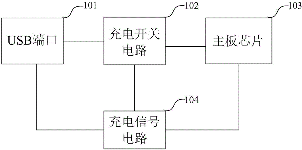
[0045] Based on the above discussion, a schematic structural diagram of a mobile terminal proposed by this application is as follows: figure 1 As shown, it includes a USB port 101, a motherboard chip 103, a charging signal circuit 104, and a charging switch circuit 102. The introduction of each important characteristic component is as follows:

[0046] (1) The charging signal circuit includes a first signal line and a second signal line, which are located between the USB port and the motherboard chip.

[0047] (2) The USB port is used to connect with the charger, and its interface includes a charging interface, a grounding interface, a first signal interface, and a second signal interface. The charging interface is connected to the charging circuit, and the grounding interface is connected to the grounding wire. By default, the first signal interface is connected to the first signal interface of the motherboard chip through the first signal line of the charging signal circuit...

Embodiment 2

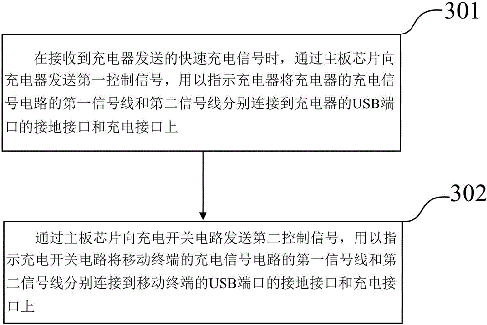
[0061] Based on the mobile terminal proposed in the first embodiment above, this application proposes a charging method for the mobile terminal, which is used to increase the current of the charging circuit and increase the charging speed of the mobile terminal when using a common USB charging cable for fast charging. Such as image 3 It is a schematic flow chart of a charging method for a mobile terminal proposed in this application. The method is applied to the mobile terminal as proposed in Embodiment 1. The method at least includes:

[0062] S301. When receiving a fast charging signal sent by the charger, send a first control signal to the charger through the motherboard chip.

[0063] The first control signal is used to instruct the charger to connect the first signal line and the second signal line of the charging signal circuit of the charger to the ground interface and the charging interface of the USB port of the charger respectively.

[0064] In the embodiment of th...


PUM


Abstract

The invention discloses a mobile terminal. The mobile terminal comprises a USB port, a main board chip, a charging signal circuit and a charging switching circuit, wherein the main board chip is used for transmitting a first control signal to a charger when a rapid charging signal from the charger is received so as to indicate the charger to connect a first signal line and a second signal lien of the charging signal circuit with a grounding interface and a charging interface of the USB port respectively, and transmitting a second control signal to the charging switching circuit; and the charging switching circuit is connected with the main board chip, the USB port and the charging signal circuit separately and used for connecting the first signal line and the second signal line of the charging signal circuit of the mobile terminal with the grounding interface and the charging interface of the USB port of the mobile terminal respectively when the second control signal is received. Therefore, the circuit resistance of the USB charging line is lowered, the charging current is greatly improved, and the rapid charging speed of the mobile terminal is increased.

Description

technical field [0001] The present invention relates to the field of communication technologies, and in particular to a mobile terminal. Meanwhile, the present application also particularly relates to a charging method, device, and system for a mobile terminal. Background technique [0002] With the development of science and technology, the charging methods of mobile terminals are gradually becoming more and more abundant. In addition to common ordinary charging methods, new charging methods such as fast charging and wireless charging have also been introduced in recent years. For different types of charging methods, the charging signal circuits are different. For example, if a common charging method is used, the charging signal circuit will generally not exceed 1.5A. However, if the fast charging method is adopted, the current of the charging signal circuit will be larger than that of the ordinary charging method, and generally needs to reach more than 2A. [0003] In o...

Claims


Application Information

Patent Timeline
Patent Type & Authority Applications(China)
IPC IPC(8): H02J7/00
CPCH02J7/007H02J7/00H02J7/00034
Inventor 宋伟娟
Owner QINGDAO HISENSE MOBILE COMM TECH CO LTD
Why Eureka
Try Eureka