Three-level full-bridge DC conversion device

A DC conversion and three-level technology, applied in the direction of converting DC power input to DC power output, output power conversion device, and adjusting electrical variables, can solve the problems of unfavorable converter efficiency, large on-state resistance, and large conduction loss And other problems, to achieve the effect of improving the utilization rate of DC voltage, improving reliability and improving efficiency

Active Publication Date: 2017-03-15
NO 719 RES INST CHINA SHIPBUILDING IND
View PDF4 Cites 9 Cited by
  • Summary
  • Abstract
  • Description
  • Claims
  • Application Information

AI Technical Summary

Problems solved by technology

The high-voltage MOSFET switch tube has large on-state resistance and large conduction loss, which is not conducive to improving the efficiency of the converter; the high-voltage IGBT switch tube has serious current tailing phenomenon, which limits the increase of switching frequency, which is not conducive to reducing the transformer and filter. Volume, weight and cost; the switching tubes are connected in series, requiring more complex circuits and controls to ensure better synchronous control and voltage equalization between the series switching tubes

Method used


Image

  • Three-level full-bridge DC conversion device
  • Three-level full-bridge DC conversion device
  • Three-level full-bridge DC conversion device

Examples


Embodiment Construction

[0034] The present invention will be further described below in conjunction with the accompanying drawings and specific embodiments.

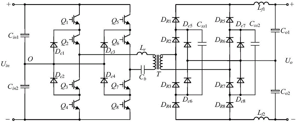
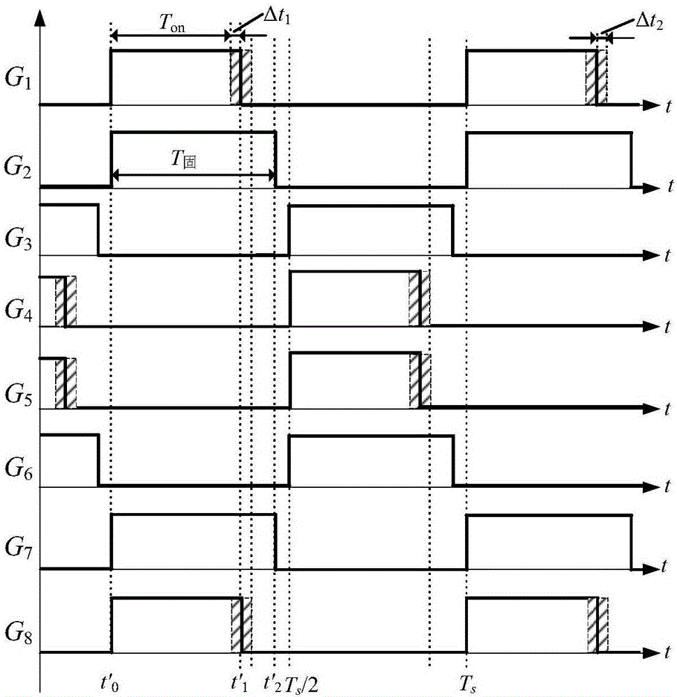
[0035] figure 1 It is a main circuit diagram of a three-level full-bridge DC conversion device according to an embodiment of the present invention. Such as figure 1 As shown, the three-level full-bridge DC conversion device in this embodiment includes: a first input voltage dividing capacitor C in1 , the second input voltage dividing capacitor C in2 , the first switching tube Q 1 , the second switching tube Q 2 , the third switching tube Q 3 , the fourth switching tube Q 4 , the fifth switching tube Q 5 , the sixth switching tube Q 6 , the seventh switching tube Q 7 , the eighth switching tube Q 8 ; The first rectifier diode D R1 , the second rectifier diode D R2 , the third rectifier diode D R3 , the fourth rectifier diode D R4 , the fifth rectifier diode D R5 , the sixth rectifier diode D R6 , the seventh rectifier diode D R7...


PUM


Abstract

The invention discloses a three-level full-bridge DC conversion device. A low-voltage diode can be directly adopted by a secondary rectifier side of a transformer of the three-level full-bridge DC conversion device to achieve high voltage output, and meanwhile, the problem of non-uniform voltage, caused by the reverse recovery inconsistency, of the diode which is directly connected in series is solved. In most of the switching period, a secondary rectifier diode is clamped by a secondary flying capacitor, so that voltage oscillation and spikes on the diode can be eliminated without adding an auxiliary circuit and reduction of the volume and improvement of the conversion efficiency are facilitated. Output voltage of a secondary rectifier bridge has certain DC bias, the secondary rectifier bridge can output higher voltage than a conventional rectifier circuit, and current ripples on an output filter inductor are smaller, so that improvement of the DC voltage utilization ratio and the power density of the device is facilitated and the volume and the weight of the device are reduced.

Description

technical field [0001] The invention relates to a DC-DC power conversion device, in particular to a three-level full-bridge DC conversion device suitable for high-voltage and high-power applications. Background technique [0002] In recent years, the application of power electronics technology in modern industrial society has become more and more extensive, and the requirements for power conversion devices have become higher and higher. Efficiency, high reliability, high power density and low cost have become the main factors for the development of power electronics technology trend. In many occasions, such as three-phase power factor correction converters, ship electrical, high-speed railway electrical, rail transit electrical, etc., their input or output voltages are high, and generally require electrical isolation. If traditional isolated converters are used , such as forward, flyback, push-pull, half-bridge and full-bridge, etc., you need to choose a switch tube with hi...

Claims


Application Information

Patent Timeline
Patent Type & Authority Applications(China)
IPC IPC(8): H02M3/335H02M1/00
CPCH02M1/00H02M3/3353H02M1/0038H02M1/0058Y02B70/10
Inventor 姚川吴浩伟李鹏汪文涛金翔李小谦邓磊刘鹏李锐蔡凯欧阳晖姜波李可维周樑金惠峰邢贺鹏徐正喜陈涛魏华罗伟雷秉霖张辉睿
Owner NO 719 RES INST CHINA SHIPBUILDING IND
Why Eureka
Try Eureka