Plastic crossbeam pipe column structure and plastic injecting and forming method thereof
What is AI technical title?
AI technical title is built by Patsnap AI team. It summarizes the technical point description of the patent document.
A technology of beam tube and column structure, applied in the field of auto parts, can solve the problems of heavy weight, no application of light weight, small cost and high cost, and achieve excellent strength and rigidity, low warpage and cost reduction. Effect
Inactive Publication Date: 2017-03-22
SUZHOU HENGYUANSHENG MOLDING CO LTD
View PDF5 Cites 5 Cited by
Summary
Abstract
Description
Claims
Application Information
AI Technical Summary
This helps you quickly interpret patents by identifying the three key elements:
Problems solved by technology
Method used
Benefits of technology
Problems solved by technology
[0004] The traditional beam column is made of iron, aluminum-magnesiumalloy and other materials. The strength and rigidity of the traditional material can meet the requirements of the beam column, but its cost is high and the weight is heavy. It should not be used in today's automotive industry for light weight and low cost. requirements
Method used
Image
Click on the blue label to locate the original text in one second.
Reading with bidirectional positioning of images and text.
Examples
Embodiment 1
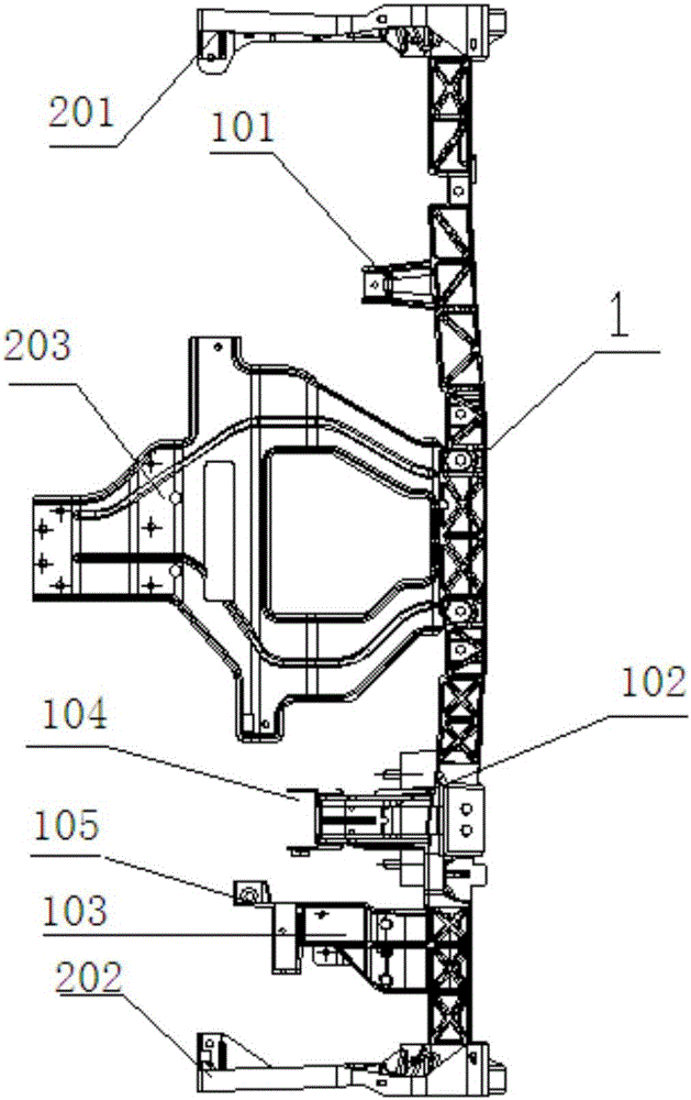
[0028] refer to figure 1 As shown, a plastic beam pipe column structure is disclosed in this embodiment, which includes: a pipe beam 1, a first connecting piece 101, a second connecting piece 102, and a third connecting piece 103 are arranged on the above-mentioned pipe beam 1, and the above-mentioned The first connecting piece 101, the second connecting piece 102, and the third connecting piece 103 are on the same side of the above-mentioned pipe beam 1, and the above-mentioned first connecting piece 101, the second connecting piece 102, the third connecting piece 103 and the above-mentioned pipe beam 1 The same material, and one-piece molding.
[0029] The first connecting piece 101 , the second connecting piece 102 , and the third connecting piece 103 are used to connect central control instruments or components, and a limiting hole is provided at the free end of the first connecting piece 101 .
[0030] A plurality of blind rivet bolts are arranged on the second connectin...
Embodiment 2
[0035] In this embodiment, the material of the first connector 101, the second connector 102, the third connector 103, and the pipe beam 1 is GVL-6H, and GVL-6H includes aromatic nylon and long fibers, and the material of GVL-6H Young's modulus is 22000MPa, Poisson's ratio is 0.4, density is 1.69.
[0036] Carry out injection molding to the beam column structure in embodiment 1, comprise the following steps:
[0037] S101 Mix and plasticize various raw materials in the material GVL-6H;
[0038] S102 melts the plasticized raw materials and forms a polymer film through a die;
[0039] S103 sends the material into the twin-screw extruder for extrusion;
[0040] S104 Press the mixed material extruded from the twin-screw extruder into the injection mold for integral injection molding.
[0041] The basic pipe beam and support part of the above-mentioned beam and column structure adopts an integral molding injection molding process. The structure has excellent strength and rigidit...
PUM
Property
Measurement
Unit
Young's modulus
aaaaa
aaaaa
Young's modulus
aaaaa
aaaaa
Abstract
The invention discloses a plastic crossbeam pipecolumn structure. The plastic crossbeam pipecolumn structure comprises a pipe beam, wherein a first connecting piece, a second connecting piece and a third connecting piece are arranged on the pipe beam; a concave fixing seat is arranged at the end part of the second connecting piece; the fixing seat is embedded in the second connecting piece to be integrally formed, and is connected with a rotating shaft of a steering wheel; a first bracket and a second bracket are respectively arranged at two free ends of the pipe beam; and a central control iron piece is arranged in the middle of the pipe beam, and is arranged between the first connecting piece and the second connecting piece. According to the plastic crossbeam pipe column structure disclosed by the invention, the basic pipe beam and the bracket parts adopt an integrated forming and plastic injecting technology; the plastic crossbeam pipe column structure has good strength and good rigidity in different temperatures and different humidity, and is low in warping and high in dimension stability; and compared with a crossbeam pipe column made from conventional materials, a plastic crossbeam pipe column disclosed by the invention has the advantages that the weight is reduced by 40%, and the cost is reduced by 15%.
Description
technical field [0001] The invention relates to the field of auto parts, in particular to a plastic beam pipe column structure and an injection molding method thereof. Background technique [0002] The instrument panel is located directly in front of the driver, and is generally equipped with a driving odometer, a speedometer, an engine tachometer, a fuel gauge, warning lights, and signal lights. The driver can not only understand the basic driving status of the vehicle through the dashboard, but also control the air vents, audio, air conditioning and lighting, so as to ensure safety and enjoy more driving pleasure. [0003] In order to ensure that the various instruments and parts supported can work normally under high-speed driving and vibration conditions, the instrument panel and the beam column supporting the instrument panel must have sufficient rigidity, and in order to reduce the impact of external forces on the front and the co-pilot in the event of an accident Imp...
Claims
Application Information
Patent Timeline
Application Date:The date an application was filed.
Publication Date:The date a patent or application was officially published.
First Publication Date:The earliest publication date of a patent with the same application number.
Issue Date:Publication date of the patent grant document.
PCT Entry Date:The Entry date of PCT National Phase.
Estimated Expiry Date:The statutory expiry date of a patent right according to the Patent Law, and it is the longest term of protection that the patent right can achieve without the termination of the patent right due to other reasons(Term extension factor has been taken into account ).
Invalid Date:Actual expiry date is based on effective date or publication date of legal transaction data of invalid patent.

