Control device for automatically drying sludge in solar greenhouse

A control device and solar energy technology, applied in dehydration/drying/concentrated sludge treatment, electric speed/acceleration control, water treatment parameter control, etc., can solve the problems of artificially judging the drying degree of sludge, and achieve automatic drying , low operating cost and high degree of automation

Pending Publication Date: 2017-03-22
SOUTH CHINA UNIV OF TECH
View PDF3 Cites 4 Cited by
  • Summary
  • Abstract
  • Description
  • Claims
  • Application Information

AI Technical Summary

Problems solved by technology

[0003] The purpose of the present invention is to solve the problem that traditional solar greenhouses need to manually judge the drying degree of sludge, and provide a control device for automatically drying sludge in solar greenhouses

Method used


Image

  • Control device for automatically drying sludge in solar greenhouse
  • Control device for automatically drying sludge in solar greenhouse
  • Control device for automatically drying sludge in solar greenhouse

Examples


Embodiment 1

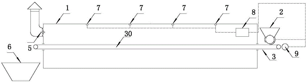
[0031] Such as figure 1 As shown, a solar greenhouse automatic drying sludge control device includes a solar greenhouse 1, a feeder 2, a conveyor belt mechanism 3, an exhaust fan 5, a storage bin 6, a heat flow meter 7, and a regulator 8,

[0032] The main body of the conveyor belt mechanism 3 is located in the solar greenhouse 1, and includes a first conveyor belt 30 driven by a motor 9, the motor 9 is connected to the regulator 8 circuit, and the feed end and the discharge end of the first conveyor belt 30 are Both extend to the outside of the solar greenhouse 1, and the feeder 2 is arranged directly above the feeding end of the first conveyor belt 30 outside the solar greenhouse 1, and the feeding amount is controlled by a regulator 8, and the staff regularly adds sludge to the feeder 2 . The storage bin 6 is arranged directly below the discharge end of the first conveyor belt 30 outside the solar greenhouse 1, and the exhaust fan 5 is arranged on one side of the solar gre...

Embodiment 2

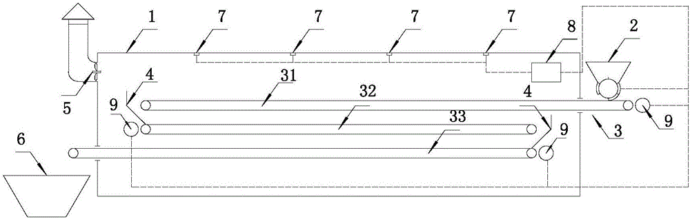
[0042] Such as figure 2 As shown, a solar greenhouse automatic drying sludge control device includes a solar greenhouse 1, a feeder 2, a conveyor belt mechanism 3, an exhaust fan 5, a storage bin 6, a heat flow meter 7, and a regulator 8,

[0043] The main body of the conveyor belt mechanism 3 is located at the solar greenhouse 1, and the conveyor belt mechanism 3 includes more than three conveyor belts driven by the motor 9, namely the second conveyor belt 31, the third conveyor belt 32, and the fourth conveyor belt 33. Each conveyor belt runs from top to bottom. The sludge is arranged in parallel with a certain distance apart, and the sludge is gradually transferred to the third conveyor belt 32 and the fourth conveyor belt 33 from the feeding end of the second conveyor belt 31 along the broken line track by gravity, and finally flows out from the outlet of the fourth conveyor belt 33. , the motor 9 is connected to the regulator 8 circuit.

[0044]The feed end of the secon...


PUM


Abstract

The invention discloses a control device for automatically drying sludge in a solar greenhouse. The control device comprises the solar greenhouse, a feeder, a conveying belt mechanism, an exhaust fan, a storage bin, a heat-flow meter and an adjuster. According to the control device, the density value of heat flow entering the solar greenhouse is measured by the heat-flow meter, and then the adjuster controls the operation of a system according to the density value to achieve the purpose of automatic sludge drying; and the control device is simple to operate, a worker only needs to periodically add wet sludge into the feeder and recycle clean sludge from the storage bin and does not need to judge the drying degree of the sludge, the system can control the drying time of the sludge in the solar greenhouse according to the density value of the heat flow entering the solar greenhouse to realize automatic sludge drying, and the control device is high in degree of automation and low in operating cost.

Description

technical field [0001] The invention relates to the field of solar energy utilization and sludge drying, in particular to a control device for automatically drying sludge in a solar greenhouse. Background technique [0002] Solar energy is a renewable and clean energy, its effective use can reduce human dependence on fossil energy, and can effectively alleviate the current increasingly serious environmental pollution problems. The amount of sludge discharged from sewage treatment plants every day is huge. If it is dried, it will have great utilization value. For example, wet sludge can be used as fuel after drying, and its calorific value is equivalent to lignite. Solar greenhouses use clean and renewable solar energy to dry indoor sludge, which is energy-saving and environmentally friendly. However, the amount of energy input into solar greenhouses is affected by the weather, and then the time required for sludge drying is affected by the weather. Whether the sludge reaches...

Claims


Application Information

Patent Timeline
Patent Type & Authority Applications(China)
IPC IPC(8): C02F11/12G05D13/62
CPCG05D13/62C02F11/12C02F2209/01Y02W10/37
Inventor 楼波蔡瑞鹏薛演振
Owner SOUTH CHINA UNIV OF TECH
Why Eureka
Try Eureka